Prepare System
Before any experiment can be performed, the system needs to be set up.
This workflow is a guide through the necessary steps. It will take up to 5 minutes and should be repeated every time a new probe is used. Advanced users can directly jump into a step by selecting it directly depending on their experiment.
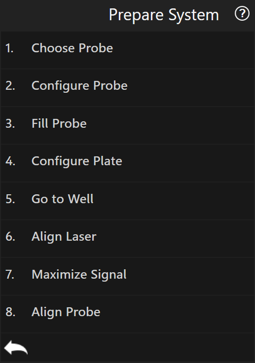
Choose Probe
In this step probes are dropped and/or gripped. Both operations can be performed in one run, so that the time during which there is no probe mounted on the system will be minimized.
Note
This step cannot be run if the worktable contains no probe holder. To update the plate configuration run Exchange Plates in the menu “Workflows”. Sample holder is always placed on the right side.
If an access to the probe holder is needed, press To Right Port (respectively -
To Left Port) which moves the plate to one of the ports.
Insert the probe into a slot:
Warning
The XY axes are controlled by linear motors with limited holding force, so place the sample and probe rack holders carefully. If too much force is applied in XY the motor may switch off and the stage has to be re-initialized by restarting the software.
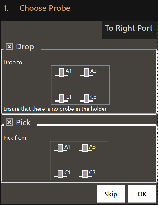
Drop
If a probe is already mounted, it must be removed first. To do so, choose an empty slot in which to place that probe by clicking on it.
Attention
Make sure that the slot used to drop the tip is empty.
Note
The checkbox ‘Drop’ is automatically checked if a probe is mounted. However,
if the system does not detect an already mounted probe a
drop operation can be enforced by checking Drop.
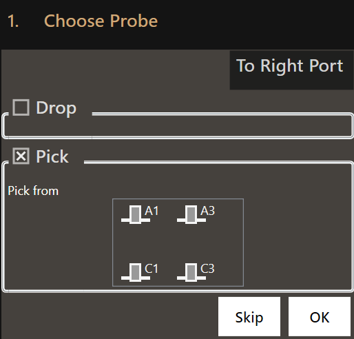
Pick
Choose the probe to be picked by clicking on the corresponding probe icon.
Press OK to start the probe exchange process.
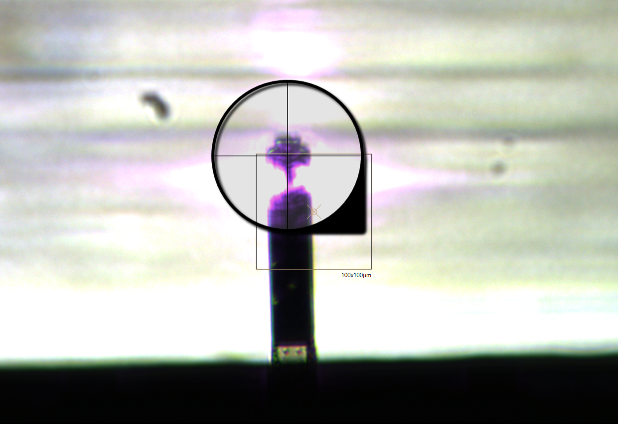
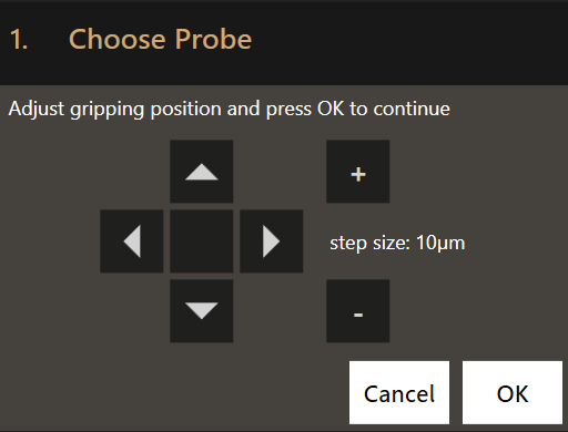
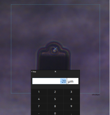
The system pauses right before the gripping operation. A rectangle is shown
to correct the positioning before the grip operation if Show Help Lines is set
to Always or DuringGripping in the
system settings. The positioning can be either
corrected by dragging the stage or using the
Navigation arrows.
Note
If the probe can’t be seen, check if the light is turned on and the bottom camera focuses on the probe. The internal illumination can be changed in the menu “Settings”, category “BOT”, parameter “Illumination”.
Example of a successful grip operation: The probe becomes blurry as it moves into the head when the gripping mechanism closes.
Air Tightness Test
After the probe has been mounted, the system automatically performs an air tightness test. It applies 20mbar and measures the average flow. If the absolute flow is greater than 0.10Pa, a warning is displayed:
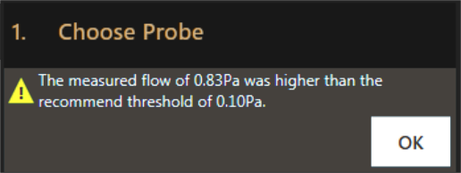
This means the probe is not correctly mounted which could lead to spillage and unreachable pressure values. To fix this, try repeating the gripping two to three times. If this does not work, refer to the troubleshooting section.
Note
If the system doesn’t support measuring flows or if the pressure controller isn’t ready, the air tightness test can’t be performed and needs to be done manually.
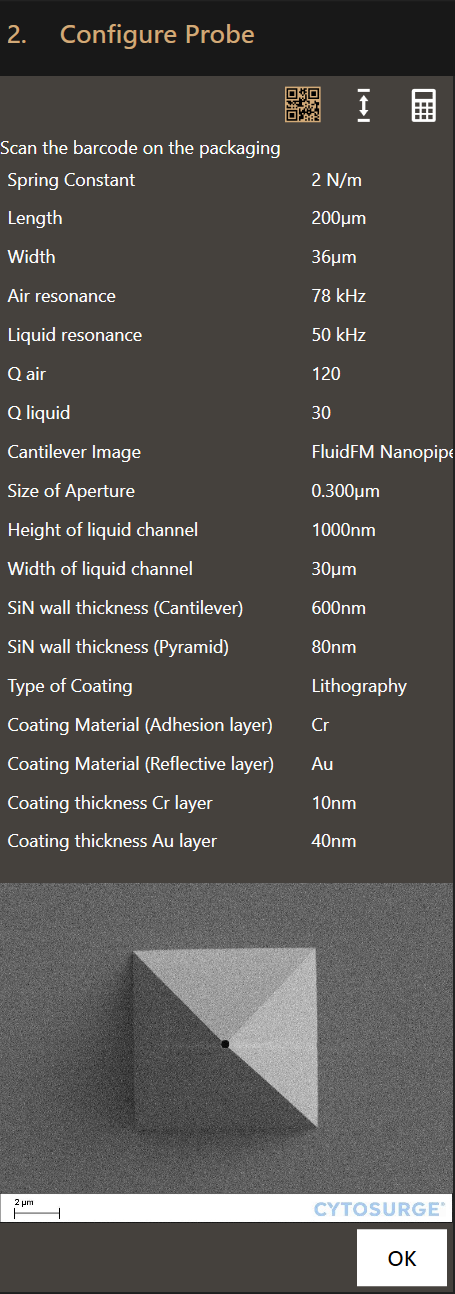
Configure Probe
Defines the probe’s specification. The values are used for subsequent calibrations.
This can be done in three different ways:
Barcode
Note
This is the recommended way of defining the probe’s specification.
Scan the barcode on the back of the package of the probe using the barcode reader to automatically download the specifications.
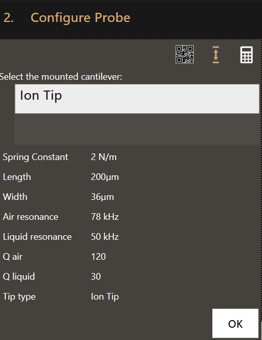
Selector
Select the mounted probe’s type from a list. No data will be downloaded using this method.
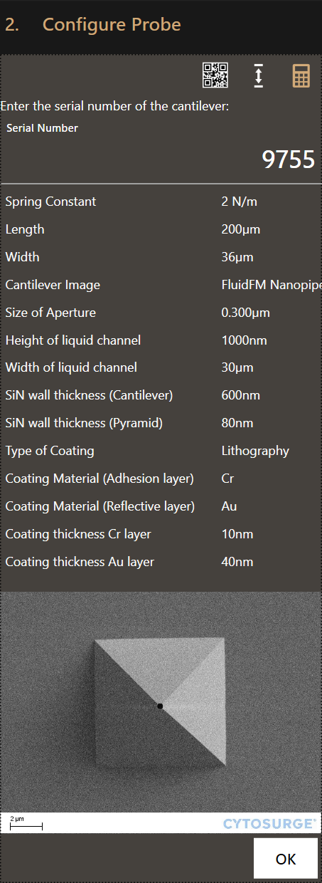
Manually
Enter the probe’s serial number manually to download the specifications.
Note
Calibration values can be directly entered in the settings menu.
Fill Probe
In this step, the probe is filled with the liquid from the container.
Further information
With air in the probe, surface (tension) effects will prevent a reproducible delivery of liquid out of the probe. Therefore it is necessary to fill the probe from the reservoir first, to both release and aspirate liquids.
-
Set the desired filling pressure using the left slider. 400-500mbar is usually enough and liquid in the cantilever can be seen within 10s after applying the pressure.
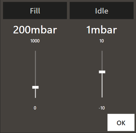
-
Apply the pressure by pressing the
Fillbutton. - Wait until a change in the filling help image is visible or use a fluorescence stain to control the outflow. Do not stop pressure application, yet.
- Move to the sample using the Navigation tool (see also the next step).
- Once the probe is in the liquid of the target well, stop pressure application by pressing the ‘Idle’ button.
- Adjust the idle pressure using the right slider until the filling remains stable (i.e. is neither pushed back into nor flows out of the cantilever).
Filling Help
The filling help takes the currently shown image and subtracts a reference image from it. In this way, changes in contrast are amplified and allow a clear determination when a probe is filled with liquid.
The example video above shows a channel being filled between second 4 and 5. The color change shown on the main video is minuscule and hard to spot. However, the difference is easily visible in the filling help video located within the Fill Probe step.
Configure Plate
Move the stage to the right port, open the lid and remove the probe holder.
Select the now exposed well plate from the list and configure the content and travel height appropriately.
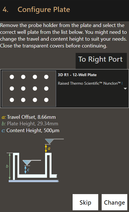
Proceed to the next step.
Warning
Don’t forget to close the transparent cover again.
Go to Well
Move to the desired well with the help of the Navigation tool.
Stop the pressure application only once the probe is in the liquid of the target well.
Proceed to the next step.
Align Laser
The laser has to be aligned with the tip of the probe for the force feedback to work.
Further information
The laser alignment has to be performed in the same medium as the experiment will be conducted. It can be deionised water if water-based solutions are used. If you change your target liquid, you need to realign and maximize the laser again for the signal to be accurate.
- Ensure that the microscope is focused on the probe
- Use the arrow navigation control in the dialog to adjust the laser beam such that it is positionned between ⅓ and ½ of the cantilever’s length from the tip, as shown in the right picture:
| Before alignment | After alignment |
|---|---|
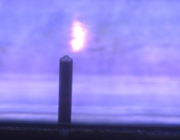 |
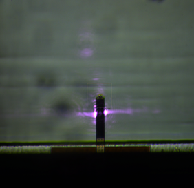 |
Press OK to proceed to the next step.
Maximize Signal
This step optimizes the signal quality.
Choose Center automatically as the system can usually perform this step on its
own. However, in case of highly reflective backgrounds or non-standard probes,
manual alignment is required.
Further information
For best force control, the signal needs to be maximized. Maximal signal is achieved when the two photo detectors receive an equal amount of laser signal. For that, a mirror inside the head has to be brought into the optimal position.
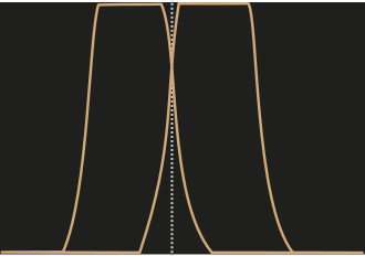
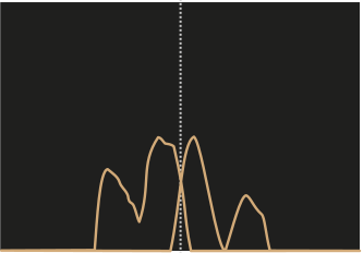
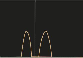
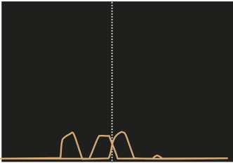
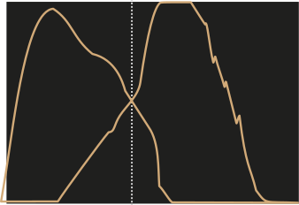
The automatic signal maximization gives a feedback with a graph showing two curves - corresponding to each photodetector signal depending of the mirror position. Their intersection is the best mirror position. Below are a few examples.
Continue by pressing OK if there are overlapping curves with continuous segments
in the intersecting area. Otherwise, realign the laser’s x/y position (previous
step).
Further information
The ideal position of the mirror depends of the refractive index of the medium used. When the liquid medium is changed, it is therefore recommended to maximize the signal again.
Good Signal
Bad Signals
Align Probe
Select the tip of the probe with the crosshair. This gives a rough estimation for the offset determined with the 3D Printing Calibration workflow and allows for more accurate printing.
The image below shows the correct position to select.