Voxel Cloud Generator tab
The Voxel Cloud Generator (VCG) tab creates print files and manages the placement of the prints on the substrate in the printing chamber.
Graphical User Interface (GUI) overview
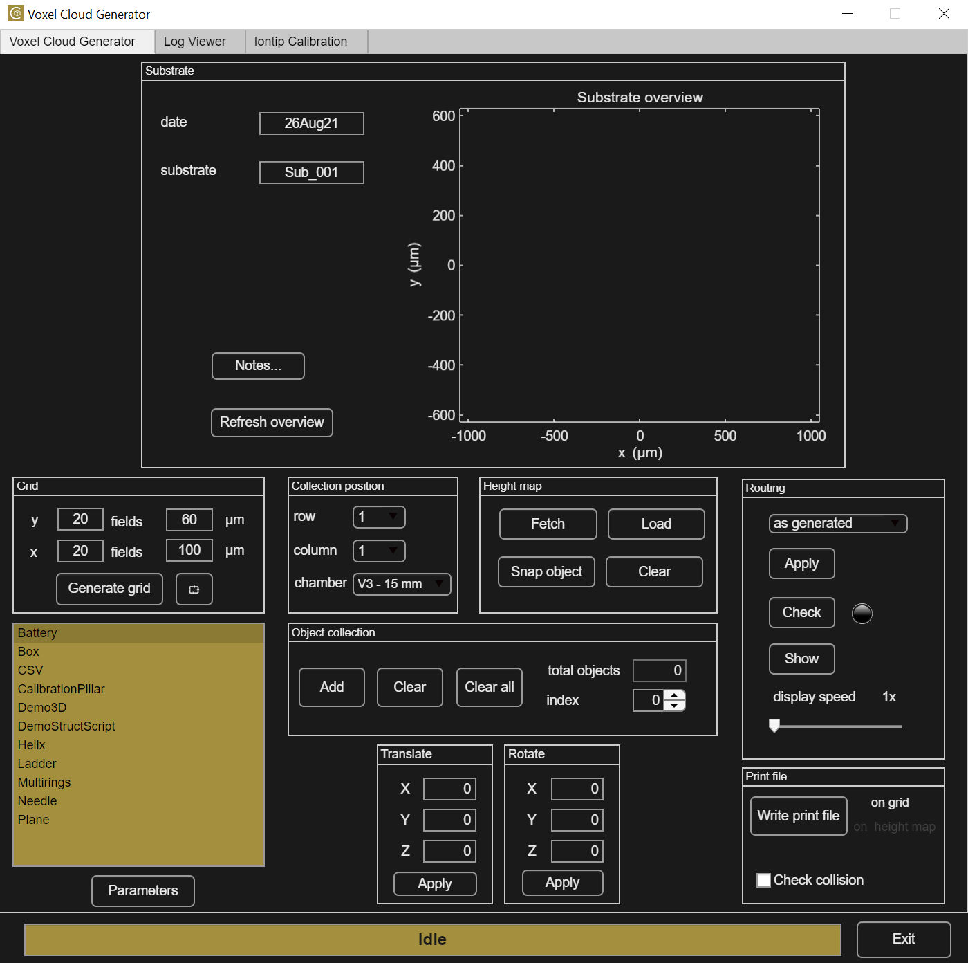
The VCG interface is divided into panels that follow the logical steps required to create a print file. The arrangement of the panels follows roughly a top-to-bottom, left-to-right sequence. Generally speaking, the sequence is as follows:
- The substrate is defined in terms of name, date and grid size.
- A position in which the structure will be placed on the the substrate is selected. Alternatively, a height map, obtained with the Mapping Workflow, can be loaded.
- Starting from the built-in scripts, different objects can be added to a collection, which is the precursor of a print file. Each object can be rotated and translated at will.
- After the collection is completed, it is possible to use routing to check and fix potential collision problems.
- The collection is ready to be finalized in a print file, which will be written either on a grid position or on a height map.
Nomenclature
Different objects obtained by editing the default scripts or loaded as CSV file can be freely combined. The resulting combination is called object collection, or simply collection, and it is displayed in the collection figure.
Defining the substrate
Substrate overview
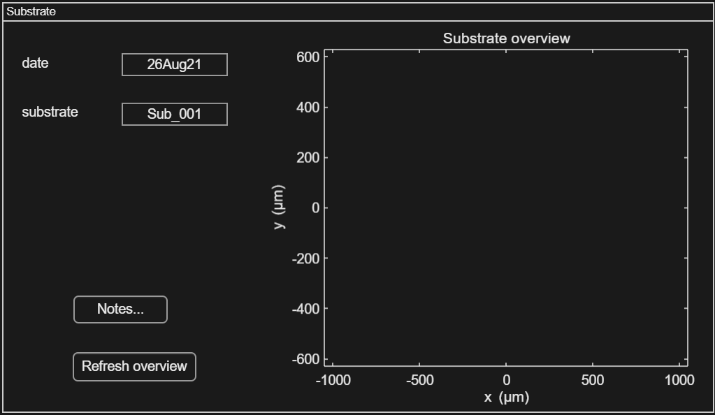
Each object is printed on a substrate and the top figure depicts the active substrate. To create a new substrate type a unique Substrate name and click Refresh overview. In case an existing substrate name is typed all associated print log files merged with the LogViewer will show up.
The grid of grey points shows the center point of each field.
Enabled on this figure are:
- box zoom (left click and drag around the area to zoom in)
- datatip (click on a field position to get their coordinates relative to the center of the substrate, row and column number)
The button Notes... creates a note file for this substrate. This function is used to write or read additional information related to the active substrate. Note files are saved in the substrate folder under /analysis.
Grid
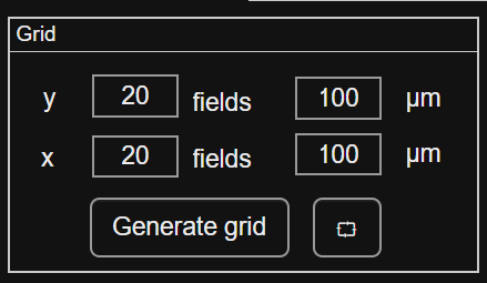
The simplest way to arrange structures on the substrate is to use a grid of virtual points.A new grid is generated by clicking the Generate grid button. The grid will
have the specified number of fields in x and in y, with the sizes of each field in µm.
The button in the bottom right corner is used to restore the default view of the grid.
Note
Each grid has descending y-coordinates increasing row numbers. To significantly reduce the canche of the iontip colliding with and damaging previously printed structures, printing of consecutive structures should be done with strictly monotonically increasing row numbers. For more information on this topic refer to Placing the structure on the substrate.
Collection positioning
Placement on the grid
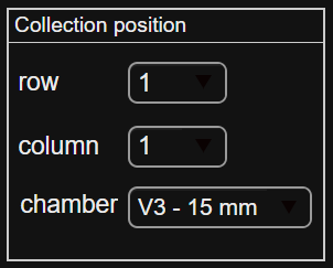
The structure to be printed will be added to the grid position,
determined by the selected row and column number amongst the fields defined in the grid panel.
The chamber refers to the printing chamber and substrate size, and it is crucial that the correct printing chamber and substrate size are selected here. This determines the absolute position of the substrate grid origin in the XY coordinate system.
The entries available and the associated coordinates are defined in ChamberList.txt located in the main directory. Please do not change origin values for default chamber entries.
Placement on a height map
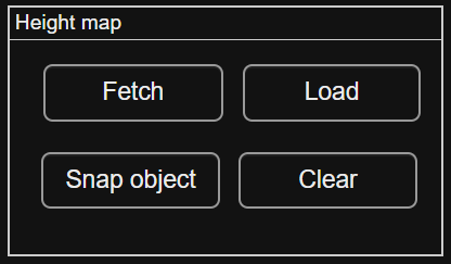
Alternatively, structures can be aligned with and printed onto existing features of the substrate. The Mapping Workflow creates a height map of the substrate. Please note that to place structures with ~5 μm accuracy the Translate and Rotate Files feature should be used.
Fetch: the height map will be moved in the /analysis/~SubstrateName~ folder.
Load: open the ~SubstrateName~ folder and select the desired height map file.
Clear: remove the current map from the collection figure.
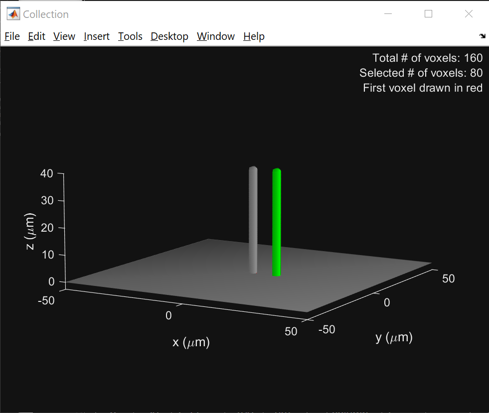
Snap object: snap the first voxel of the collection object is to the closest xyz coordinate of the height map.
Note
The first voxel of the collection is plotted in red in the collection figure.
Creating the object collection
Script panel
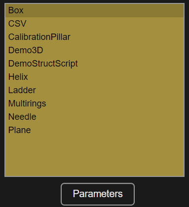
Scripts generate voxels according to a parametrized design or shape. If a script is selected, the Parameters button can be clicked to access those parameters in the parameters editor window. A preview becomes available with the voxel diameter estimated from the active iontip calibration curve. All the scripts available by default with the app are described here.
The combine buttons
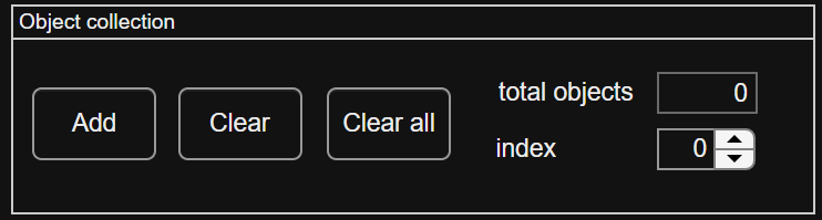
The Add button adds the structure that is defined by the selected script. Objects added to the current design can be viewed in the collection figure.
The Clear button removes the active object (current index object, plotted in green in the collection figure).
The Clear All button removes all structures from the current design.
Total objects counts the number of objects in the current design. The Index allows to change the active object, plotted in green, used for the clear, translate and rotate actions.
Translation and rotation
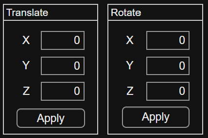
Translate and rotate enable transformations on the active object by the amounts specified in the panels. The center of rotation is [0,0], origin of the design.
Note
Translation and rotation are also applied to any new object added to the design.
Routing
The routing is very important, as it specifies the sequence in which the voxels are printed. By default, voxels are printed as-generated, in the order they are added in the design. Objects are sorted by index number and voxels in an object are printed in the order generated by the script used.
This default routing could lead to collisions when multiple objects are added to a design or if a script generates voxels in a non optimal order. Multiple options are available here to solve those issues:
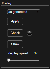
There are several routing options. Click Apply to reroute the voxels:
-
as-generated- The voxels are ordered as they were ordered at the time of adding the object(s) to the collection.
-
z- The voxels are sorted in +z only. The x and y sequence remain the same (for the same z coordinate).
-
x-y-z- The voxels are sorted in +z, then in +y and then in +x. So, the tip routing is first in +x, then in +y, then in +z.
-
y-x-z- The voxels are sorted in +z, then in +x and then in +y. So, the tip routing is first in +y, then in +x, then in +z.
-
auto correct- Solve possible collisions by rerouting voxels with the minimal number of changes before checking the collision status again. More than one iteration of correction may be needed with this method to remove all collisions. The routing may fail if too many iterations are needed.
Two additional features for the routing management can be used:
-
Check- Simulate the printing sequence to check the possibility of collision of the tip or consumable with the design itself. The lamp
 turns red
  if collisions are detected, or green
  if the design is estimated safe to print. Another routing option should be applied if collisions are detected.
-
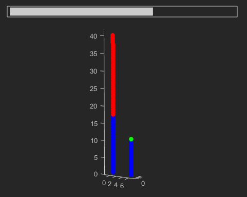
Show- In a new window containing a figure, the printing sequence is simulated. The green voxel represents the current position of the tip. If at any time during the simulation voxels turn red, a collision was detected and a routing correction is necessary. The
display speedslider can be used to vary the simulation speed. The speed value gives the number of voxels plotted at each frame (1-100). Closing the figure window stops the simulation.
Depending on the routing selected, the pressure in the final print file can change as the printer goes from one voxel to the next. It should be considered that the response time of the tubing system can be up to a few seconds. For example, a pressure that changes every voxel may not be followed by the system and can lead to a constantly changing and unexpected flow at the iontip.
Generating the printfile
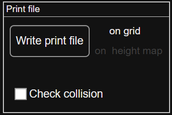
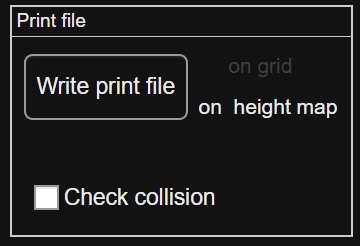
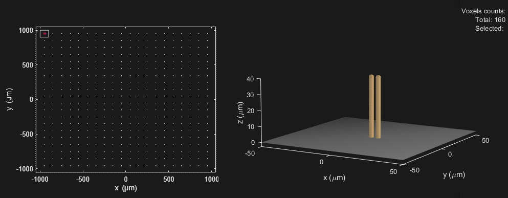
The Write print file button converts the current collection to a new print file. Voxels turn gold in the collection figure, the first voxel remains red.
First voxel
The xy coordinates of the first voxel determine where the iontip will approach to the substrate surface at the start of the print.
Depending on the position selected, either on the grid in a specific row and column or on a height map, the correct text is heighlighted (left on grid, right on height map).
The substrate preview figure is updated with the printed structure in its position (row 1 column 1 in this example).
Collision check
Check this box to do a collision check upon clicking the Print button.
It checks whether any collision of the probe including its
plastic holder will occur with structures already printed on the same substrate.
The routine will check against all merged print files present in the substrate folder. In case of collision, the print file will not be created and a message is displayed in the status bar. If printed structures being bent or smashed is of no importance, uncheck this option and click Print again to generate the print file.
Status bar
The bar at the bottom of the VCG shows the latest app status.
