3D Printing Calibration
This calibration is necessary to align the iontip position, which changes from tip to tip, with the center of the top view system.
Set up the 3D Printing Calibration workflow
Navigate to the 3D Printing Calibration workflow.
There are two ways to use the 3D Printing Calibration workflow.
- Print a structure and align using the newly printed structure.
- Align using a previously printed structure (the print file used must be available).
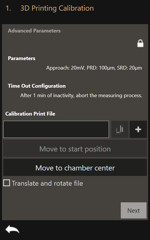
If you would like to print a structure within this workflow (option 1.), the same preparation applies as for regular 3D printing. Please refer to the 3D printing workflow for the explanation of:
- Parameters
- Time Out Configuration
- Adding a Calibration Print File
- Translate and rotate file
Any print file can be used for the 3D Printing Calibration workflow. We recommend to use a simple pillar.
If you choose option 2., load the print file of the previously printed structure under Calibration Print File. There is no need to set the correct parameters for printing in case of option 2.
Start the workflow
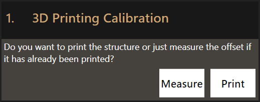
After preparing, click Next. Click Print to print the calibration structure
before measuring its offset or Measure to measure the offset of an already
printed structure.
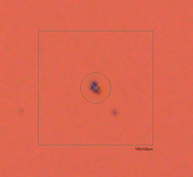
Measure the offset
With a printed calibration structure available, now measure the offset by dragging on the video feed to align the center of the video feed on the structure.
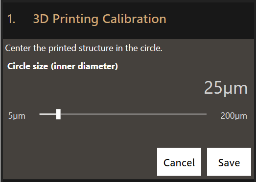
Click Save. The measured offset will be automatically applied to all future
print runs.
Log Files
The 3D Printing Calibration workflow outputs the same log files as the 3D Printing workflow.