Cabling and Wiring
This section refers to the connections between the potentiostat and the printing chamber. This information is particularly useful for troubleshooting connection problems.
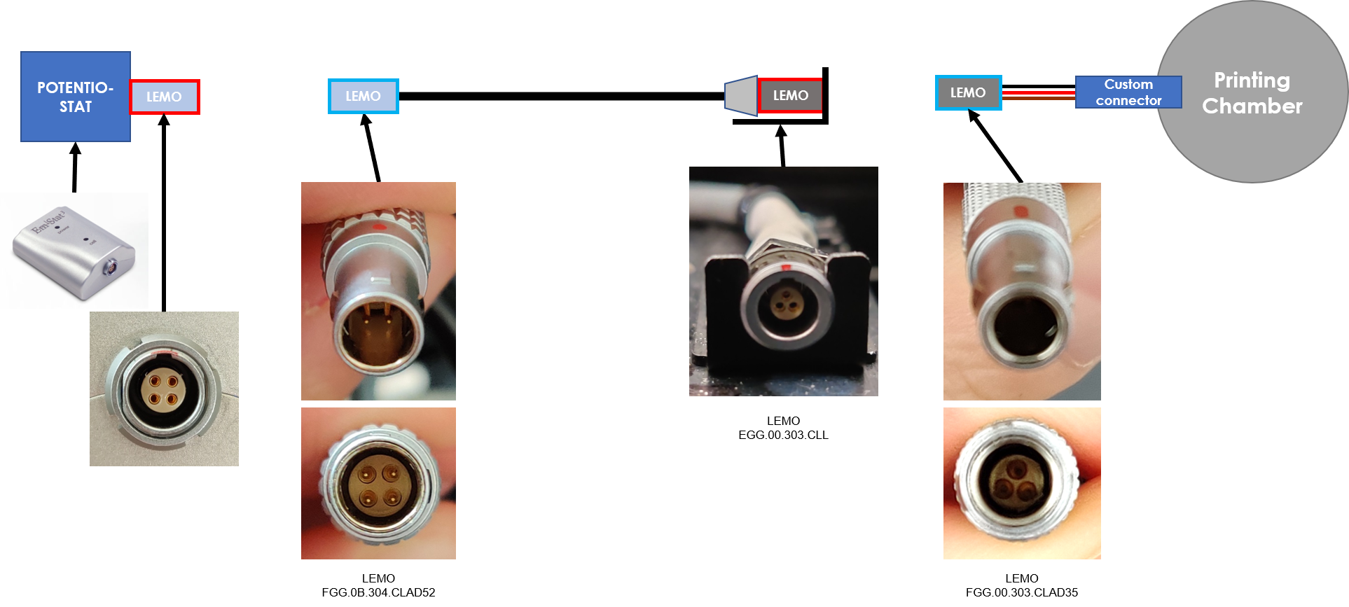
General arrangement
In the system, high quality, insulated LEMO connectors are used to link the different components. The general arrangement is depicted below.
Legend
![]() = 4 pin connector ¦
= 4 pin connector ¦
![]() = 3 pin connector ¦
= 3 pin connector ¦
![]() = female connector ¦
= female connector ¦
![]() = male connector
= male connector
The components are the following, in order of connections:
| Component | LEMO Connector |
|---|---|
| Potentiostat | 4 pin female |
| System cable (potentiostat side) | 4 pin male |
| System cable (sledge, on system) | 3 pin female |
| Printing chamber (sledge, on system) | 3 pin male |
| Printing chamber (plate) | custom electrodes |
Note
To measure a connection with a female LEMO pin, insert a piece of stiff wire in the pin.
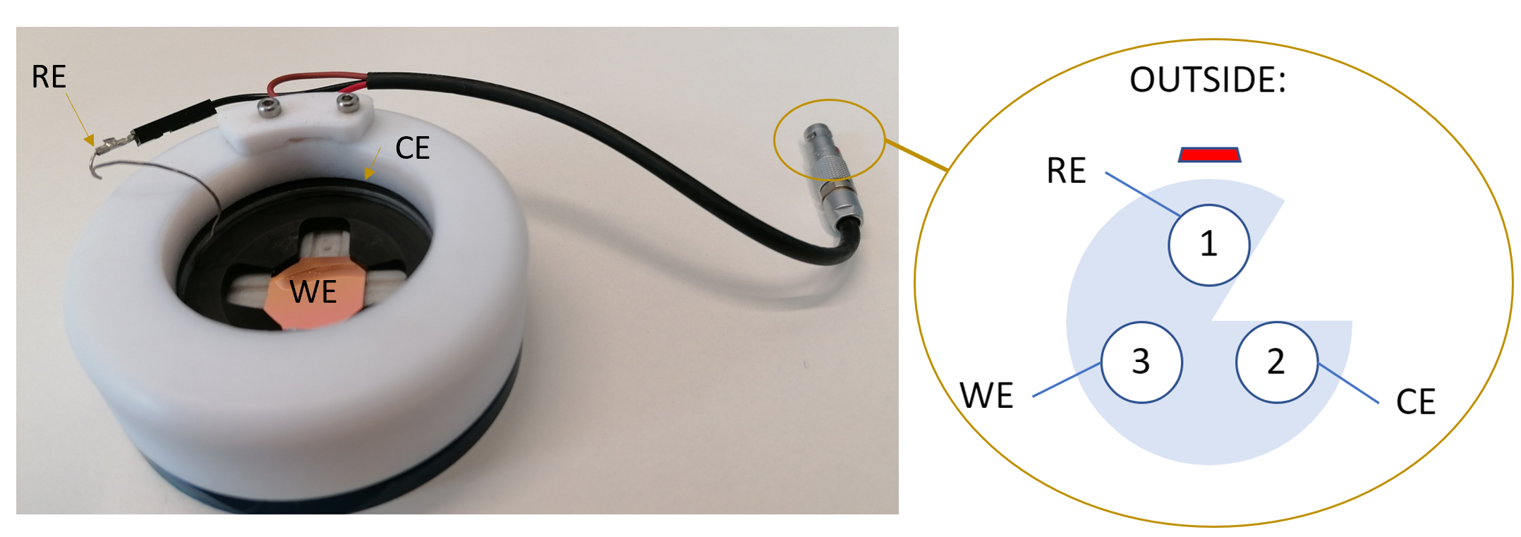
System cable connections
Each pin on the system cable is dedicated to a specific electrode.

Legend
WE = Working Electrode, RE = Reference Electrode, CE = Counter Electrode
Printing chamber cable connections
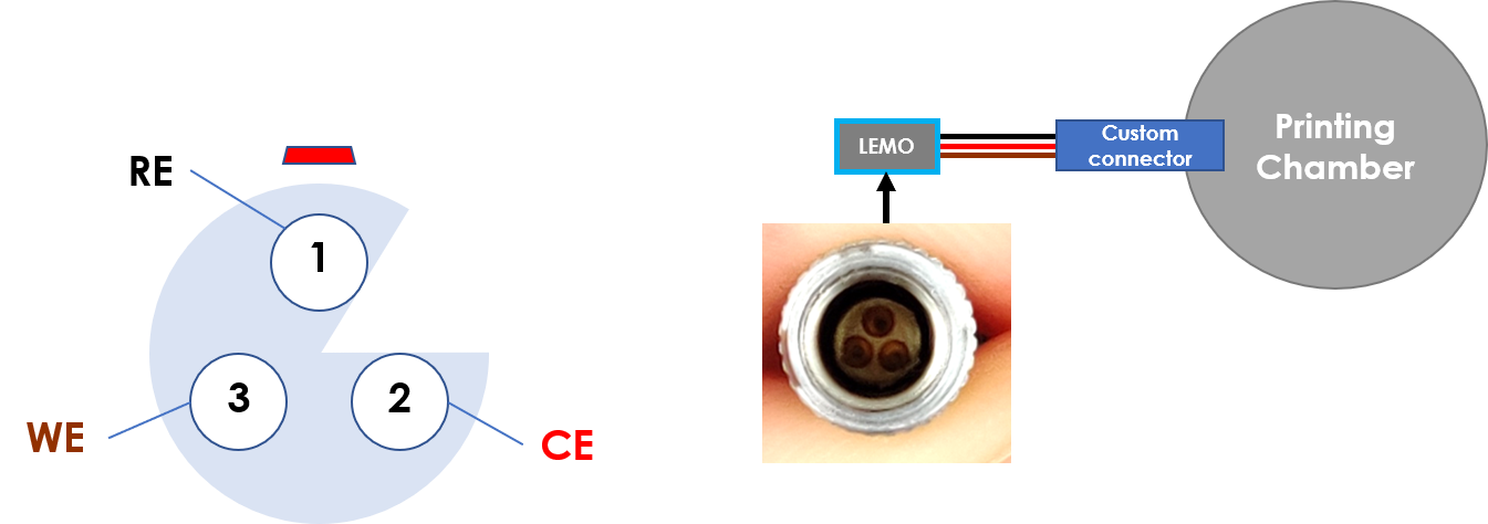
Legend
WE = Working Electrode, RE = Reference Electrode, CE = Counter Electrode
From the LEMO connector three wires connect directly to the electrodes in the printing chamber. The color convention for the wires is indicated in the figure.
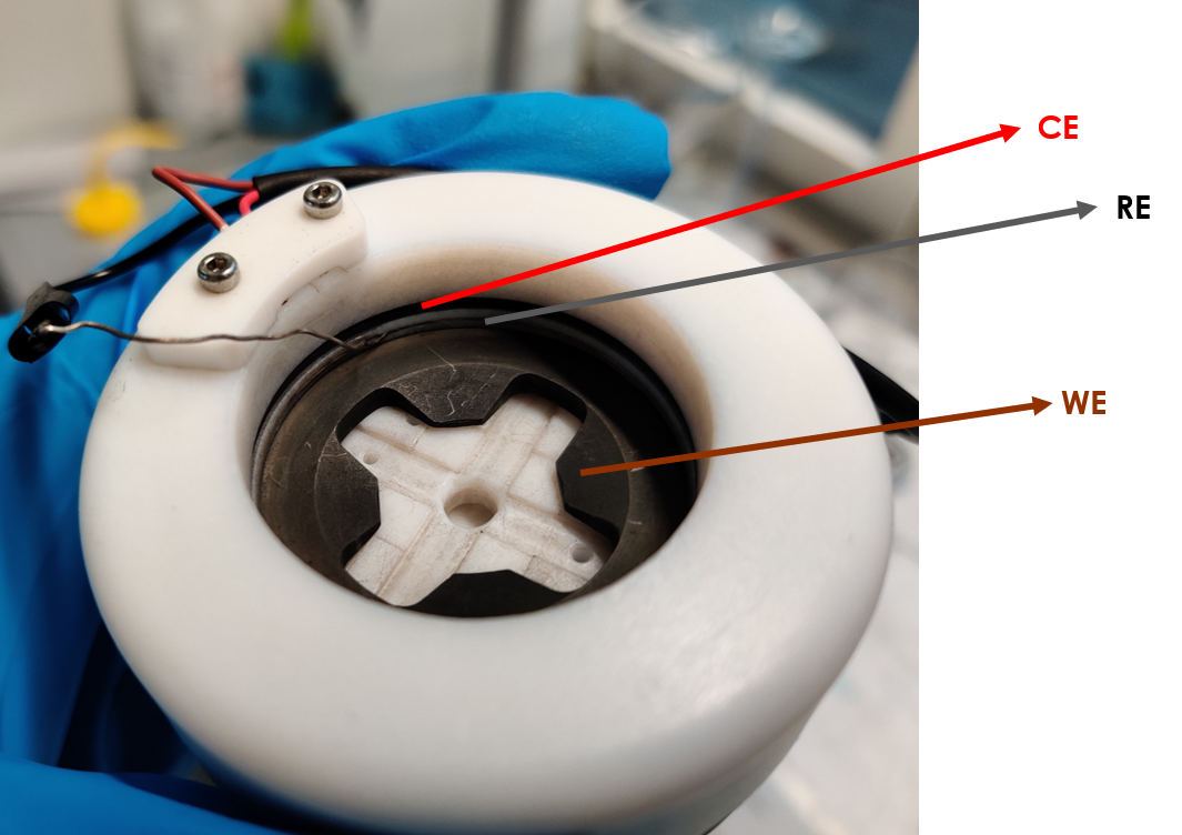
Testing the connections
After assembly, we sugest to check the connections from the 3 pin lemoplug to the printing chamber. The resistances should be as follows:
- The working electrode substrate to the bottom left pin. Target <10Ohm
- The counter electrode to the bottom right pin. Target <10Ohm
- The reference electrode to the top pin. Target <10Ohm
- The working electrode substrate to the counter electrode. Target >1MOhm
- The working electrode to the reference electrode. Target >1MOhm
- The counter electrode to the reference electrode. Target >1MOhm