Iontip Calibration
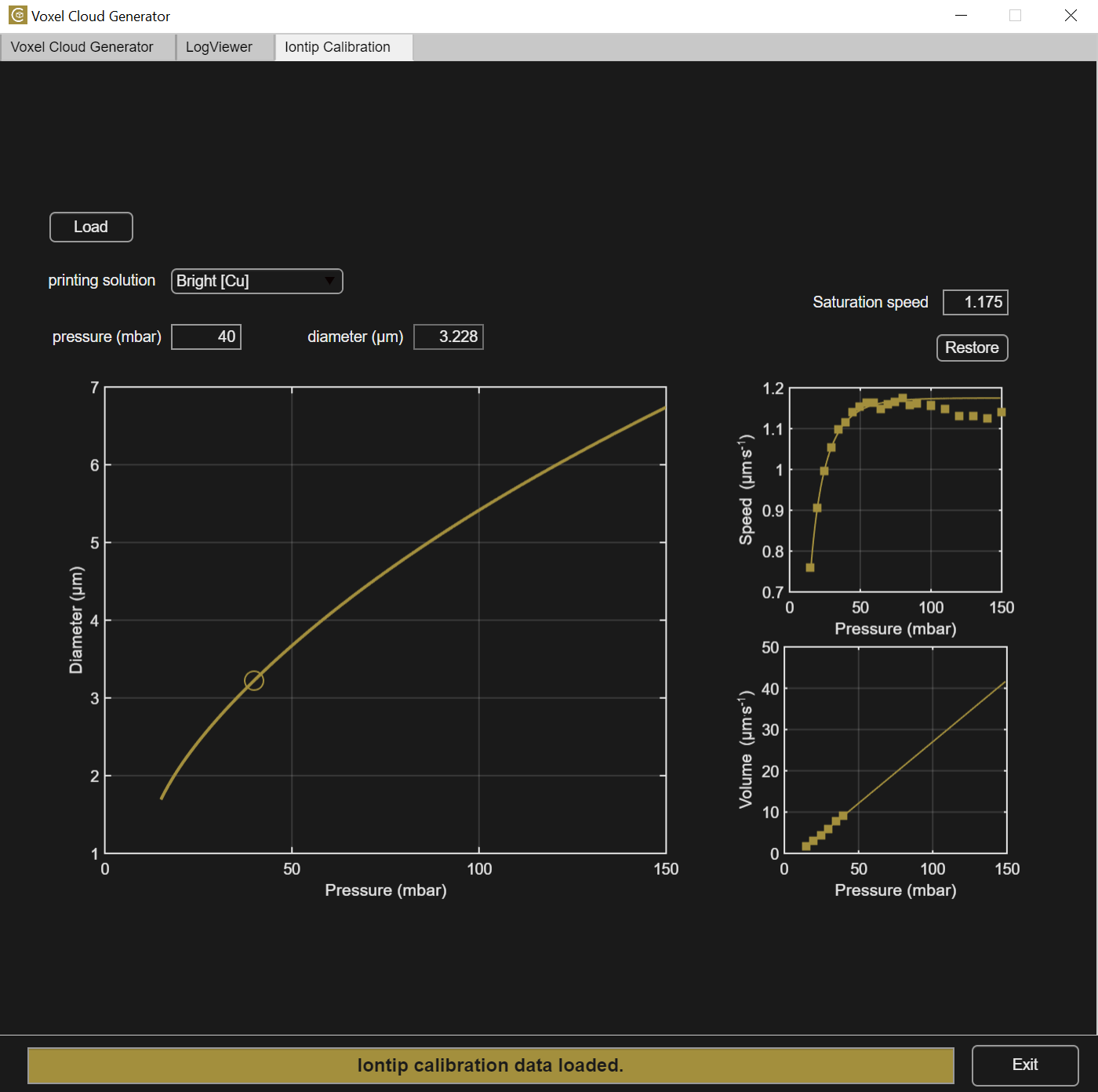
The Iontip Calibration determines the pressure - voxel diameter relation based on printed calibration pillars.
The largest graph shows the a good approximation of the pressure-pillar diameter relation, called the calibration curve. The pillar diameter is also referred to as the voxel diameter. Note that the real voxel diameter for more complex structures than a pillar will not be exactly the same. For example, when printing merging voxels in 2D (plane, wall) or in 3D (solid body), or when printing close to a non-conductive area the notion of voxel diameter changes. Nonetheless, the pillar diameter (or voxel diameter) is a useful and repeatable measure that is also used in design rules for geometries beyond a pillar.
First, one or multiple .mat report file(s) from any substrate folder are loaded using the load button. To generate such report files, use the LogViewer app. Make sure all loaded files are reported as 100% finished and use only pillars or calibration pillars with identical voxel pitch. The calibration procedure may otherwise give wrong results.
The two small graphs on the right show the plating speed and the volumetric deposition rate as functions of the pressure. The dialog box and the Restore button is used to fine-tune the saturation plating speed (plateau at high pressures) and obtain a better fit of the calibration data.
Enter a pressure value (in mbar) in the corresponding dialog box to update the corresponding diameter box according to the calibration curve.
The calibration is ink dependent and the correct ink must therefore be chosen under printing solution. The condition and age of the ink may also influence the accuracy of the calibration. For an accurate calibration, do not use expired inks.
Calibration Procedure
When varying the pressure, the plating speed - pressure relation always display a typical shape:
- Starting at 0 mbar applied (no flow), the plating speed (growth rate of a voxel in µm/s) quickly increases with the pressure, then saturates at a given pressure called the saturation pressure.
- The volumetric deposition speed (the volume of copper deposited per second) has a linear relationship with pressure.
Therefore, the calibration of an iontip requires the measurement of printing speed at different pressures applied to flow the ink. Pillars need to be printed to gather enough data points in the regime around the saturation pressure to reconstruct the pressure-diameter relation. The calibration pillar script performs a pressure ramp for this purpose. For more accurate results the section size is chosen larger. The box script is used to perform the calibration with individual pillars. A series of pillar at different pressures is printed. All pillars are then loaded together for the iontip calibration.
The calibration pillars should have at least 8 different pressure sections betweeen 30-150 mbar. The potential must not be changed during a calibration pillar print. It is recommended to print one or two pillars at roughly 100 mbar to get an iontip flowing in steady state before printing calibration pillars. Then, print immediately after, at least two calibration pillars and check for consistency. Normally the last calibration curve is the most accurate.
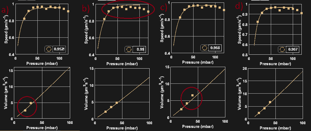
Once the data are loaded, an automatic fit is executed. For example in figure a) below, the plating speed-pressure curve is not nicely fitting the experimental data points, and only 2 points are available for the volume-pressure curve fitting. In that case, the user should adjust the saturation plating speed in the dialog box to best fit both curves. Figure b) was adjusted with a too high saturation plating speed despite the volume-pressure curve fitting being good. Figure c) has a good speed-pressure fit but a poor volume-pressure curve fit. Figure d) shows a correct calibration, fitting both speed and volume - pressure curves.
Remember to select the correct printing solution in the dropdown menu.
The iontip is now calibrated and the pressure edit box can be used to enter a pressure, the resulting diameter is shown. The VCG automatically updates its underlying calibration curve and displays the voxel size (e.g., in the collection figure) based on the currently active iontip calibration.
Note
If too few points are available on the volume-pressure curve fitting, consider adding data at lower pressures: extend the pressure list to lower pressures in the calibration pillar parameters or print additional pillars at lower pressures.
Note
It is often observed that the speed goes slightly down at the highest pressures. These data points can be safely ignored while fitting. The data points that are transferred to the volume-pressure curve are decisive for the eventual diameter-pressure curve.