Printing with the CERES system
This is an overview of the complete printing process with the CERES system. This is intended as a general guideline, but more information are available in other sections of the manual.
Prerequisites
In order to create a print with the system, the following prerequisites need to be met:
- The hardware components are switched on
- The system is calibrated
- The ioninks solutions are ready
Prepare printing chamber
Instructions on how to prepare the printing chamber are found here.
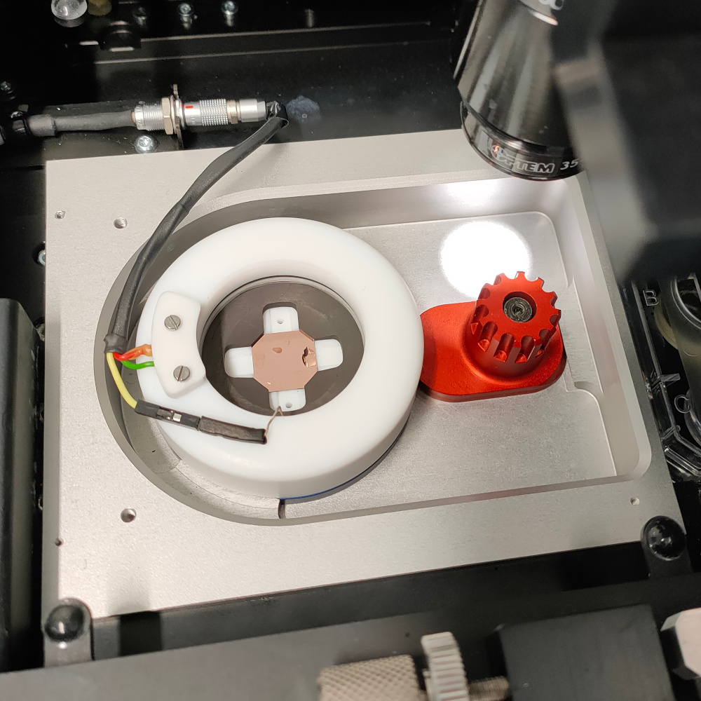
The printing chamber is assembled and placed in the system
Prepare probe
Instructions on how to prepare the probe are found here.
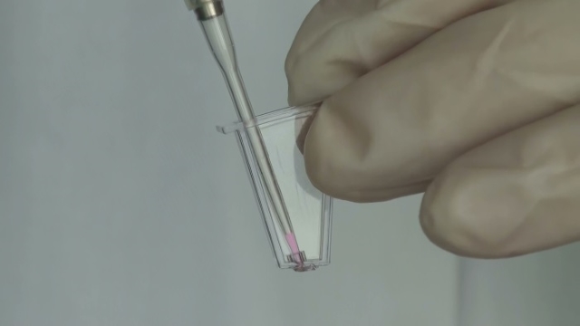
Correct filling of the probe
Prepare system
After probe preparation the tip needs to be filled with the ionink and the laser aligned on the cantilever. In order to perform these operations, follow the Prepare System workflow.
After this step the system is ready to print. Create a printfile
Creation of printfile is performed with the VCG. Using this MATLAB application, one can define structures starting from a list of built-in scripts that can be combined together.
The design of printfiles can follow different principles. Please refer to the following section for a detailed explanation of the design rules.
3D printing
Iontip calibration
Before proceding with any print, the iontip pressure-diameter characteristic needs to be calibrated. This calibration allows for precise prediction of the resulting voxel diameter when applying a specific pressure. This calibration is necessary for each tip because, due to variabilities in each tip shape, the real ink flow at the tip cannot be known a priori.
In order to calibrate the iontip it is required to print a calibration pillar, created with the VCG, using the 3D Printing workflow. After the print, the log files should be fetched (see below) and loaded in the Tip Calibration app to obtain the calibration curve.
Printing
Once the printfile(s) has been designed, it can be printed using the 3D Printing workflow. In case precise alignment of the structures is required, please first calibrate the relative position of the iontip and the camera with the 3D Printing Calibration workflow. This will allow to use the top camera view to place structures on a specific spot on the substrate (with a precision of 2-6 micrometers).
It is advised to place structures on the substrate following a left -> right, top -> bottom arrangement.
Logs
Once a print job is finished, the software generates log files. These files can be opened using the MATLAB app LogViewer. For some more info on how to interpret log files please refer to the Troubleshooting section.