3D Printing
Prerequisites
It is mandatory to successfully execute the following workflows before starting a print:
Additionally, the tip position can be calibrated using the 3D Printing Calibration. This calibration is required for printing on existing structures.
Windows updates
It is recommended to install any windows updates before starting a print, or the computer might reboot unexpectedly resulting in sample loss.
Printing in a nutshell
Navigate to the 3D printing workflow:
- Set the right configuration options
- Add at least one print file to the Print List
- Optionally translate and rotate files
- Start printing
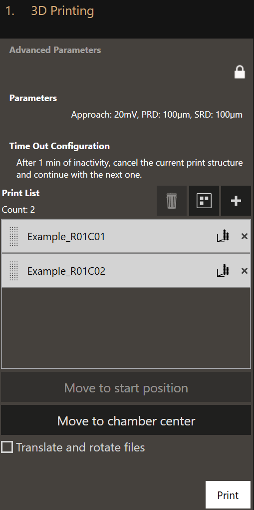
Configuration options
Advanced Parameters
The Advanced Parameters are only available after clicking on the lock icon. The Advanced Parameters should only be used after instruction or special training by Exaddon Customer Support. These parameters are therefore not explained here.
Parameters
Clicking on Parameters will open a dialog in which the standard parameters for the
printing can be set. All changes are lost every time the software is closed.
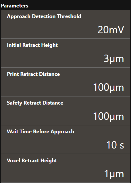
- Approach Detection Threshold
- The cantilever deflection setpoint in Volts that has to be reached when the system first approaches the sample before printing. The iontip will approach the sample at (X0, Y0). If the Approach Detection Threshold has been reached, the software defines the current z-position as Z0.
- Initial Retract Height
- After the iontip has reached the substrate surface at (X0, Y0, Z0) it retracts the distance specified here and continues to the first voxel location at (X1, Y1) travelling at the Initial Retract Height above the substrate surface (=Z0).
- Print Retract Distance
- To avoid collision when moving from one print structure to the next one, the iontip is retracted from the substrate surface by this distance before laterally moving to the start position of the next structure.
- Safety Retract Distance
- The iontip retracts by this distance after a print structure has been completed. This helps preventing collisions with already printed structures. When an idle pressure above 0 mbar is used, raising this distance can prevent unwanted plating as well as iontip clogging after a print structure is completed.
- Wait Time Before Approach
- The time to wait after 0 mbar has been applied but before the approach starts. This prevents false deflection detections as the chamber solution may not have settled down before the approach.
- Voxel Retract Height
- The distance by which the iontip retracts from a voxel each time a voxel has been completed. 1µm is recommended for standard 3D printing.
Time Out Configuration
- If the printing process comes to a halt, the system waits the specified amount of time before executing a time-out action. You can choose one of the following actions:
- Abort the whole printing process
- Pause the printing process
- Cancel printing the current structure and continue with the next one
- Cancel printing the current structure and pause the printing process
Add print files
Clicking on + opens up a file selection dialog. You can add any number of
print files.
Click and drag the dotted area left of the print file name tag to reorder manually. Clicking on the graph icon on the right of the file name tag gives a 3D visualization of the voxels in the print file.
Move to start position
Moves the top view system to the start position of the currently selected print file.
Move to chamber center
Moves the printing chamber center underneath the top view system. This center is usually also the center of the printing substrate.
Translate and rotate files
Apply a transformation (translation and rotation) to each file. This allows you to reposition a print file to any position within the accessible area of the substrate.
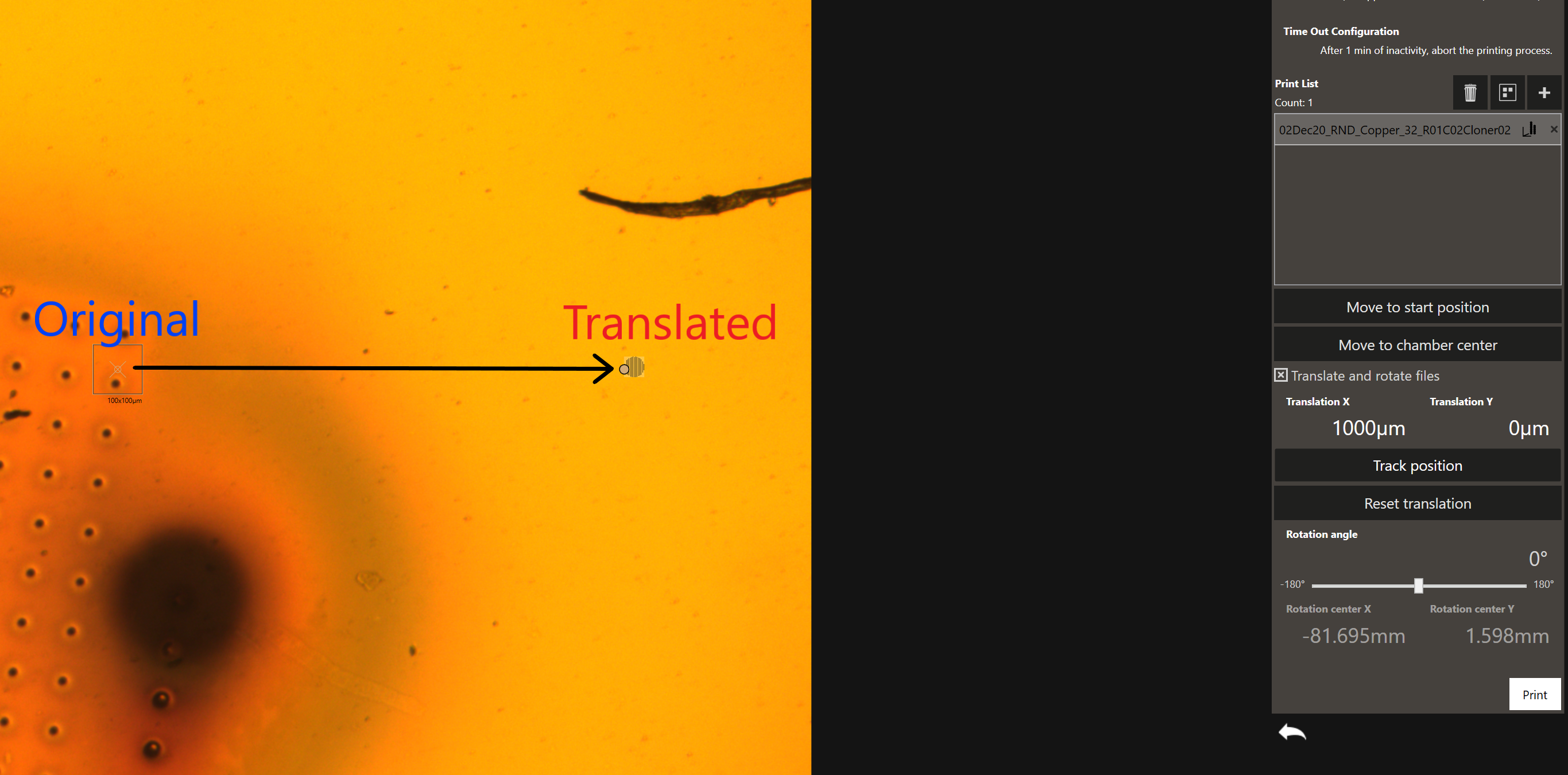
Using the Translate and rotate files feature structures can be precisely placed onto the substrate. This is particularly useful if the substrate contains existing features, such as conductive lines, onto which should be printed.
To precisely place a structure with this feature, the iontip position with respect to the top view system needs to be calibrated using the 3D Printing Calibration workflow.
The structures can be moved either by translating by specific amounts, or by clicking on Track Position and dragging on the screen.
The precision achievable with this method is around 3 to 6 μm. For higher accuracy (~ 1 μm) the Mapping workflow can be used.
Start printing
Clicking Print will immediately start the printing run. The printing can be
started at any iontip position and continues until the last print file in
the task list has been printed.
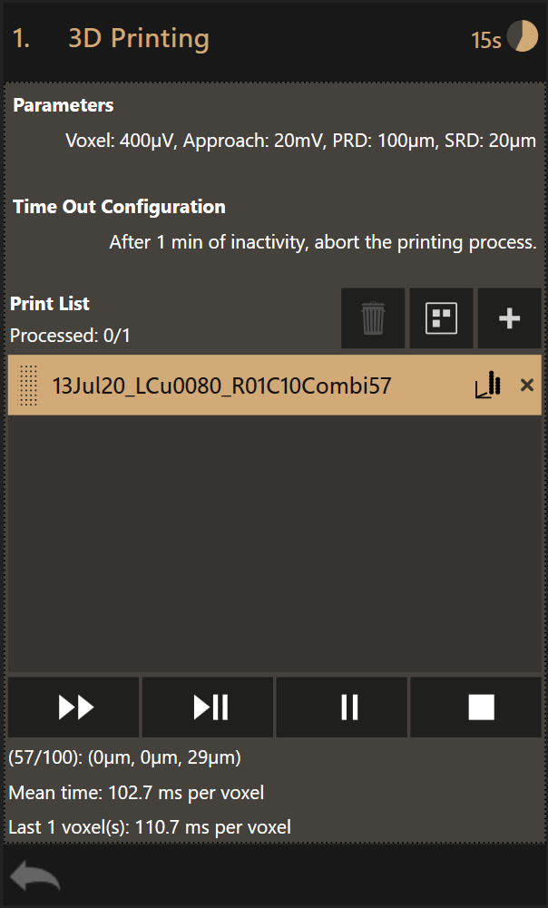
Progress monitoring
The progress monitor contains several items:
Also during printing more print files can be added to the task list. To remove a print file from the task list, click on the X mark on the right of a file name tag.
To change the order of the print files, click on the dotted area of a print file entry and drag it to the desired position.
The four controls displayed at the bottom of the dialog will (from left to right):
- Skip a file and continue with the next
- Pause and abort current
- Pause after current
- Abort printing
While printing is paused, the parameters and time out configuration can be changed.
A print file that has been printed will be grayed out in the list.
As soon as the printing stops, the files that have been printed will be removed from the task list. The files that have not been printed remain in the list.
At the top right the estimated print time remaining is shown.
At the bottom, a count down timer shows the active voxel as a fraction of the total amount of voxels in the current print file. Voxel 57 out of a total 100 voxels is being printed in this example. The location (x, y, z) of the active voxel and the mean time, calculated over the already printed voxels, are displayed.
The last voxel duration is shown as well. In case the voxel print duration was very short, the aggregated printing time of multiple voxels is displayed.
The name of the active print file is highlighted. Clicking the graph icon on the right displays a 3D rendering of the design.
Note
The Z coordinate of the active voxel gives valuable information about the iontip - sample separation. If the system does not print, it could be that the Z coordinate specified in the .csv file is incorrect. It should be very close (few 100 nm to max. a few µm from the surface).
Log Files
The workflow produces three different log files per print file. All files are
saved to %USERPROFILE%/Documents/Exaddon/Print Data.
The information contained in the log files can be accessed with the LogViewer