Plate Editor
This standalone software is installed with the CAPA control software and allows creation of custom plates which can later be used in the control software.
Overview
The software is split into three main areas:
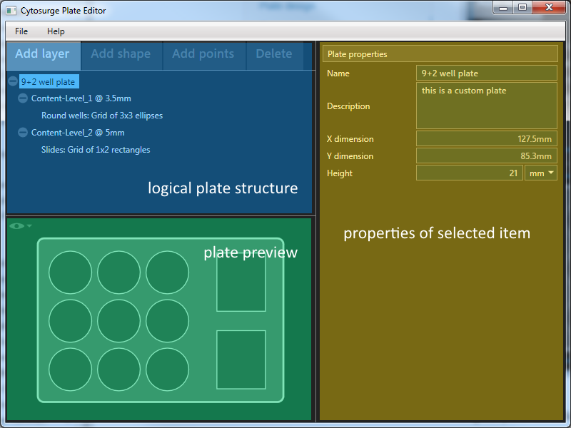
Logical plate structure
This area displays the hierarchical plate structure and supports addition and deletion of layers, shapes and points. The corresponding buttons always affect the currently selected item.
Properties view
This area displays the properties of the item currently selected in the hierarchical plate structure.
Plate preview
This area contains a live preview of the plate structure as seen from top.
Click on the  icon
to get access to view options that control the degree of details displayed.
icon
to get access to view options that control the degree of details displayed.
Plate design
The software uses a layer-based approach to design plates, where each layer corresponds to the Z-level of plate contents.
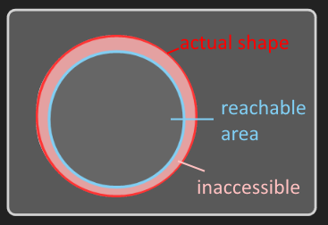
Each layer may then contain one or more shapes that define the X/Y area(s) where the contents are located. Within each shape, the head may move freely without rising to the travel offset defined in the control software. Typically, on a multiwell plate, a shape corresponds to one well minus a margin that is not reachable by a probe.
To simplify the editing process, shapes can be arranged in a uniform grid.
A shape in turn may contain a single grid of points that serve as targets within the shape to which the head can be navigated in the control software. If the shape containing the grid of points is part of a shape grid, then all the shapes in the grid contain an identical grid of points.
Note
A shape with a height or width less than 10mm does not support relative positioning. If the shape does not contain any points, the CERES controller will always navigate to the shape’s center.
Important
All coordinates and positions are tip-centric and must be reachable by the head without collision. The control software does not perform any collision checks.
The dimensions of the head can be found in the sample holder guide to correctly calculate the size of a shape.
Positioning
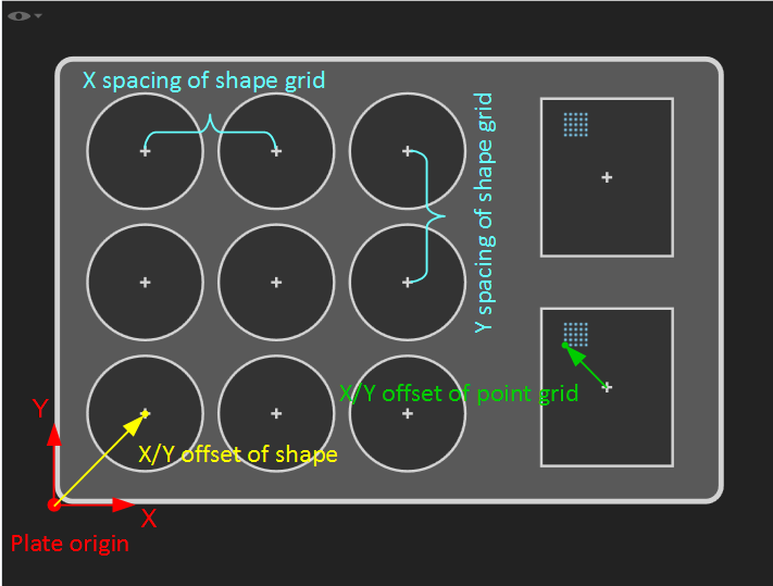
The following conventions apply for positions on the plate:
| Level | Origin | Positioned relative to |
|---|---|---|
| Plate | front left corner at the bottom of the plate | |
| Shape | center of the shape | plate origin |
| Points | the point itself | origin of the containing shape |
Grids grow in positive X and Y direction, hence their origin always coincides with the origin of the grid’s front left shape/point.
Restrictions
Plate size
Please refer to the sample holder guide for physical limitations of the plates.
Supported shape geometries
Shapes can only be circles or rectangles.
Number of shapes
The total number of shapes (or wells) on the plate is limited to 384.
Intersections
Shapes must be located completely within the plate’s bounds and must not overlap each other; points must not be located outside the shape. The software automatically detects violations of this rule and displays an error message upon violation.
Integrating the plate into the control software
On start, the control software scans a special directory in the file system and loads all plates therein. The plate editor software can save plates directly to this directory, such that they become available when the control software is started the next time.
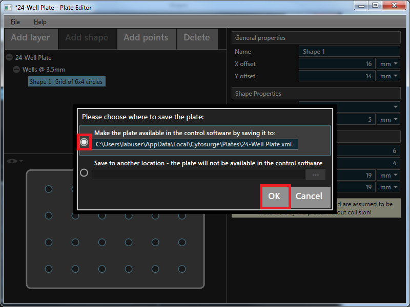
When saving a new plate, the software will ask whether to make the plate available in the control software:
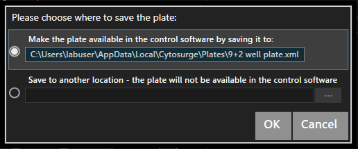
The plate will be saved with the displayed name (based on the Name property of
the plate) unless a plate with the same name already exists. In this case a
different name must be provided or the plate with the same name will be
overwritten.
Important
Please double check the plate before choosing this option, as the control software is unable to detect collision risks and may crash the hardware into the plate if the plate is not properly modeled.
Note
The plate location is bound to the user that is running the control software. Therefore the plate editor software will only save plates to the correct location when run by the same user.
After a plate is made available to the control software, it can still be edited by choosing the corresponding option when the plate editor is started. After making changes to such a plate, the control software needs to be restarted before the changes become effective.
Removing a plate from the control software
If a plate should no longer be available, the plate has to be manually removed from the control software’s plate directory. The directory defaults to:
C:\Users\<username>\AppData\Local\Exaddon\CAPA\Plates\
where <username> is the username of the account used to run the control
software.
Example: Creating a 24-well plate step by step
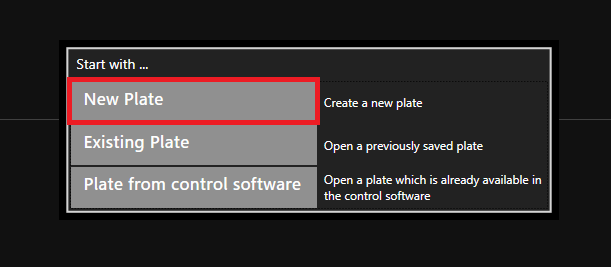
Open the plate editor and create a new plate.
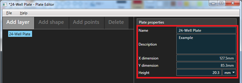
Name and describe the plate appropriately. We measured the plate to be 20.3mm high.
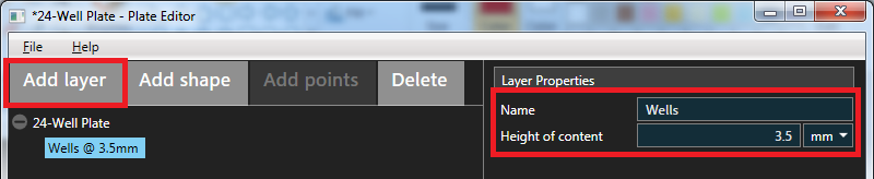
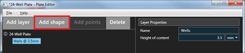
Add a layer to the plate. Its content height is at 3.5mm.
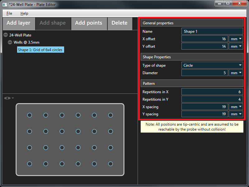
Next, add a shape to represent the wells to the layer.
The wells are evenly distributed over the plate and always the same size. We can just add one circle und let it repeat over its x and y-axis. The diameter of the wells is actually 16mm but because we only model the tip-reachable part of a well, we subtract 11mm to be safe.
This plate does not provide any predefined points.
Once we are sure that the plate is correct, we can save it via File - Save As … to make it available in the control software.