Tools & Settings
Tools
Toolbar
The toolbar is located on the left side of the main window and gives quick access to a set of functions described below:
| Tool | Name | Description |
|---|---|---|
 |
Scalebar | Toggles the scale bar at the bottom of the sample display |
 |
Navigation tool | Tool to navigate the worktable |
 |
Take screenshot | The screenshot can be exported later in different formats |
 |
Pressure tool | Manual pressure control |
 |
Oscilloscope | Shows signal streams |
 |
Probe tool | Manual z positioning |
 |
Wash tool | Save and run wash cycles |
 |
Accessible Plate Area | Displays bounds of accessible plate area on video feed |
| Potentiostat tool | Controls the potential applied to the printing chamber | |
 |
Show Result Data | Shows recorded data (e.g. screenshots) |
Navigation tool
Basic functionality
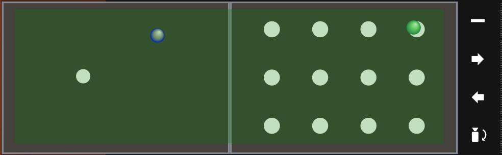
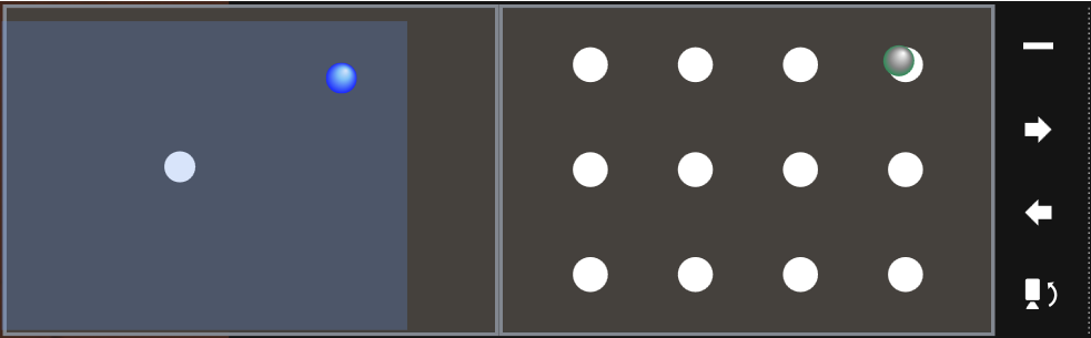
The navigation tool shows the current position of the head and the top view system on the installed plates. The position of the top view system is presented as a blue circle, while the position of the head is presented as a green circle. Only one of the two points can be active in the navigation tool, the inactive one is greyed out.
When the head is active a green transparent rectangle presents the area that can be accessed by the head. When the top camera is active a blue transparent rectangle presents the area that can be accessed by top view system. By clicking on a location, the head or the top view system will move to the selected location.
The functions of the 4 buttons offered by the navigation tool are (starting from the button placed on the top): minimize tool, move to right port, move to left port, toggle camera.
Positioning
A well containing a point pattern can always be approached with absolute positions. Simply click on the well and select the position in the dialog box which just appeared. These wells are marked by a point pattern.
The dialog box allows the user to move to:
- the well’s center
- the point pattern’s center
- any point in the point pattern
- a point relative to the well’s center
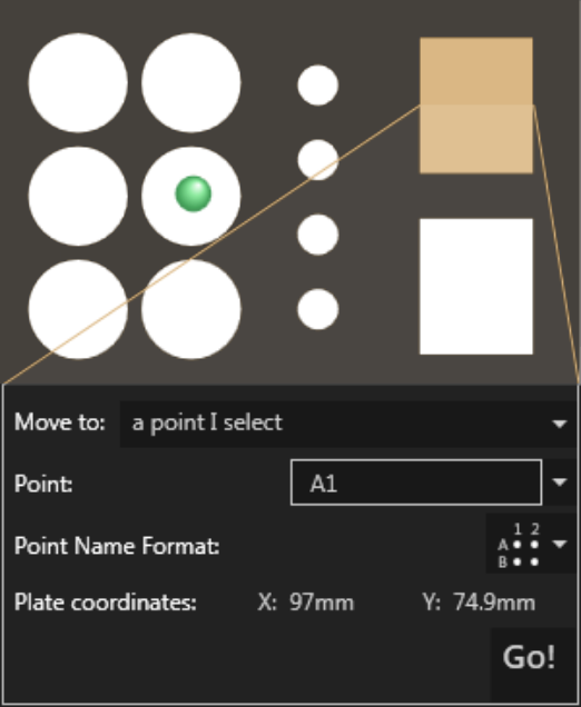
If a well does not contain a point pattern, the CERES controller will always move to the center of the well.
Note
To use custom plates, have a look a the plate editor to create a model for the CAPA Operator Software.
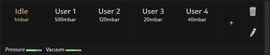
Pressure tool
This tool allows to directly control the pressure applied to the cantilever. The currently active pressure is highlighted in gold.
Adding, editing or deleting custom pressure values can be performed by using the corresponding buttons on the right.
 Add
Add
Adds the current target pressure to the list of custom pressure values. The pressure value can be directly changed using the number pad. Custom pressures are maintained between restarts of the controller software.
 Delete
Enters deletion mode: When in this mode, clicking on a custom pressure will
delete it.
 Edit
Edit
Enters edit mode: When in this mode, clicking on a custom pressure allows
its value to be changed. If an active pressure value is changed, the new value
is applied immediately.
Oscilloscope
The oscilloscope icon toggles an animated graph which displays the deflection and the pressure of the last few seconds.
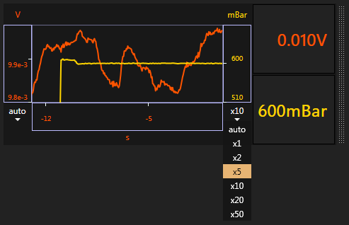
Right next to the graph, the current values of the deflection and the pressure can be seen.
The scaling of the rulers on either side can be adjusted. By default, it will automatically scale to show all recent values. If a fixed total range is desired, the zoom can be extended by expanding the zoom combo box and choosing a value. Additionally, the mouse scroll wheel can be used to scroll through all available zoom levels.
Note that the deflection signal always shows uncorrected values. Therefore, one will observe a corresponding shift of the signal when applying a relative setpoint but the signal itself will not necessarily correspond to that setpoint.
Probe tool
Control the movement of the probe using the following options (left to right):
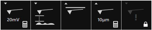
- Approach
- Pressing triggers an approach operation to the configured setpoint; pressing the icon again aborts the operation
- Move to content height
- Pressing triggers a movement to the corresponding plate’s
content height. Pressing the icon again aborts the movement. - Home position
- Retracts the cantilever to the uppermost position. Pressing the icon again aborts the movement.
- Retract
- Retracts the probe by the configured distance. Pressing the icon again aborts the movement.
- Advance
- Moves the cantilever quickly towards the sample; a second click aborts the movement. Due to the high crash risk, the operation must first be unlocked by clicking on the lock.
Wash tool
A wash cycle can be set up for the probe using the wash tool, either in the sample rack or in dedicated wells of a 12 well-plate (Well A1 to C4).
- Fill empty, unused wells with chosen washing solutions
- Define a dipping time and a pressure value
- After the last step, the probe stays in the last container to avoid the drying of the probe
As an example:
- Bleach in well A2, 5s at 100mbar
- Water in well B2, 30s at 10mbar
- Water in well C2, 2s at 0mbar, the probe will stay here as long as it has no new command
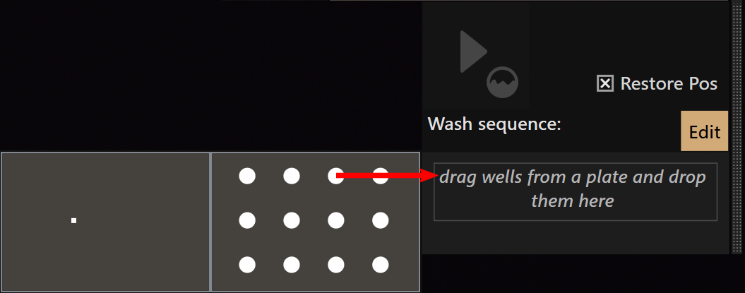
Creating a wash sequence
A wash sequence can only be edited if the plate view is visible on the left side
of the wash sequence. If the plate view is not visible, click on the Edit
button.
- To add a new wash step to the sequence: Click on a well in the plate view and
drag it to the sequence.
- To change the pressure or duration of a wash step: First select the step to
modify, then click on the property to edit.
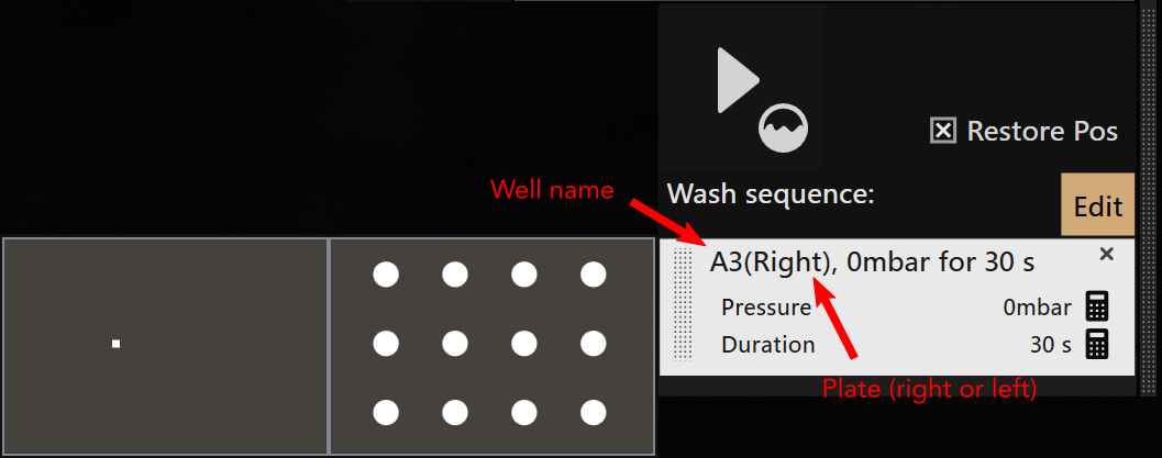
- To change the position of a step in the sequence: Click on the dotted area of a step and drag it to the new position.
Click on the  button
to start the wash cycle.
button
to start the wash cycle.
Restore Pos remembers the position of the probe before starting the wash cycle
and moves the probe back to this position once the wash cycle finishes.
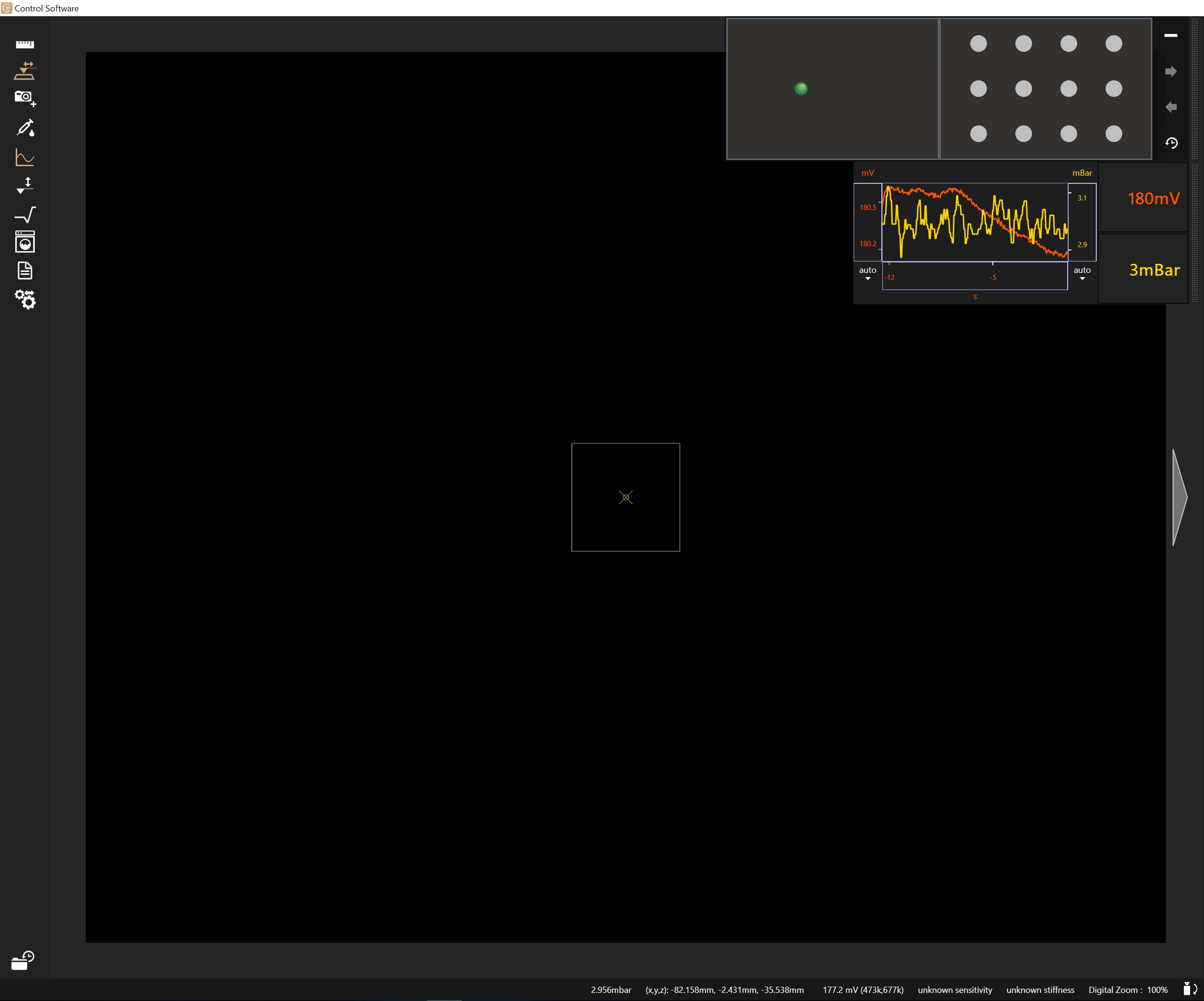
Accessible Plate Area
By activating this tool, the video feed will show the bounds of the accessible plate area. Inaccessible areas are indicated by crossing red lines.
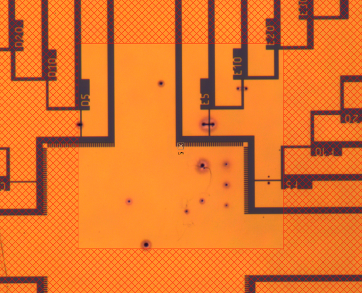
This tool is activated automatically when using the preview functionality in the 3D printing workflow.
 Potentiostat tool
The potentiostat tool allows to control the potential applied to the printing chamber. At the same time, it displays the measured values of potential and current read by the potentiostat.
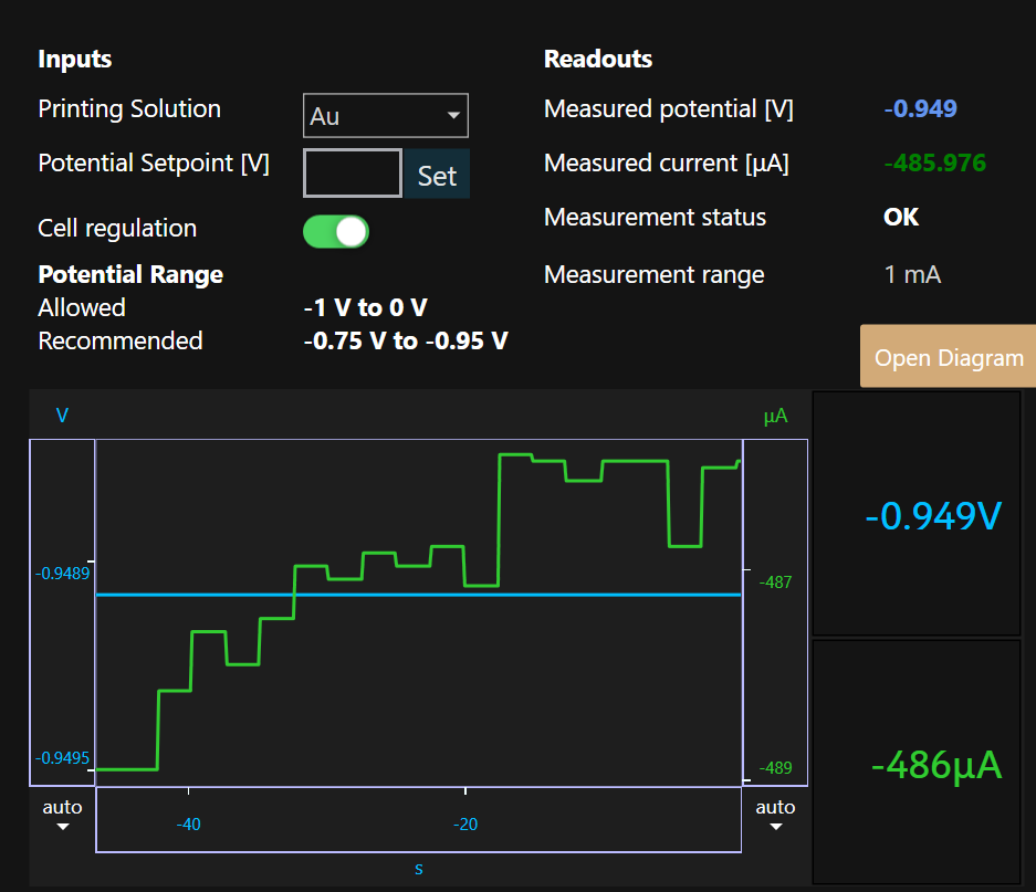
The tool is composed by the following sections:
- Inputs: Select the current printing solution and potential setpoint. Different printing solutions will have different values of allowed and recommended potential, shown below. The potentiostat cell can also be switched on or off using the toggle button.
- Readouts: In this section are shown the values of potential (in V) and current (in μA). They are useful to check that the printing chamber is working properly.
The measurement status is also shown here. This refers to the different resistors that the potentiostat uses to achieve a correct current reading. Simply put, the potentiostat can read an accurate value of current only if the measurement status is
OK. It can take several seconds to reach this status, during which the different resistors (indicated underMeasurement Range) are exchanged automatically. - Potential Range: Shows the currently suggested and allowed potential range.
- Diagram: Is a plot the values of current and potential over the last minute. It can be shown or hidden.
Result history
All results (such as screenshots and probe images) are stored in the database.
Clicking a preview icon or thumbnail will open an enlarged view with the full details of the result. This will also provide the option to export the results to a file.
The result history offers different view modes, which can be chosen at the bottom of the result history:
 Single column
Displays the result previews in a compact single column next to the tool bar.
 Extended column
Displays the result previews in a single column as above, but with a few informative details:
- An ID of the result in the database
- The date and time (in minutes) when the result was acquired
- The time since the first result was acquired
 Multiple columns
Displays the result previews i/n multiple columns, such that more results are visible compared to single column mode. In this mode, you can export all results at the same time.
System Information
At the bottom of the application window, system status information is displayed.
- Currently applied pressure
- Current axes position as an (x ,y ,z) tuple. Note that erroneous values might be reported while an initialization procedure takes place.
- Currently measured ADC values and the resulting cantilever deflection. The deflection value might differ from the one shown in the oscilloscope because here the underlying ADC values are not normalized.
- A warning if the intensity of the cantilever’s deflection value drops below a certain threshold. This might be caused by disturbances within the laser path which implies a disabled force control mechanism. The warning is only supported after the laser was aligned and its signal maximized.
- Whether a probe is mounted
- Currently used sensitivity and stiffness values
- A control to digitally magnify the video feed
- The exchange camera button to switch between the top and bottom view camera
video:

- The measured potential and the measured current (they are presented only when the potentiostat is connected)
Result export
Results of the current experiment can be exported from the result history in various ways:
- A single result can be exported from the detailed result view (after clicking on a result preview in any of the views)
- All results can be exported from the multi-column view
Click on the export button to present the following dialog box showing the export options and file path:
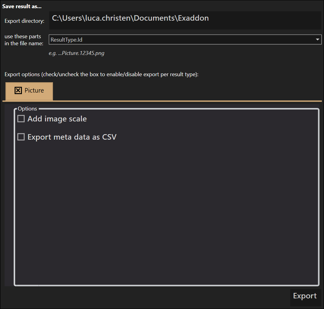
Click on the export directory to change the directory where the result data is saved. If this path is too long to display, it will be truncated - hover the mouse over the path to see the full one.
The default name of the exported files includes the result type and the unique database ID of the result in the name.
Finally, the export option dialog allows the user to select which results are exported and offers a few export options depending on the result type.
Dragging
Some tools are overlaid over the video feed. These can be moved by dragging the black handle bar on their right side.

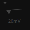
Cancellation
Buttons that start an operation usually also terminate it on a subsequent click. This is indicated by a red cross which overlays the button when cancellation is possible.
An example with the approach button:
| State | Description |
|---|---|
 |
An operation is ready to be started |
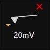 |
The operation is running - press again to abort |
 |
The operation is currently not available; either it is being stopped or another operation is running |
Arrow navigation
In various situations (e.g. during Laser Alignment) fine grained control over a movement is necessary. In this case an arrow navigation tool as depicted will be available.
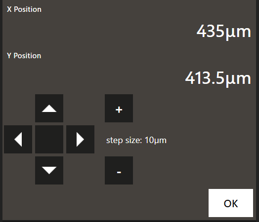
Clicking on the arrow keys will perform a movement in the corresponding
direction by the distance indicated on the right by step size. The step size
can be changed with the + and - buttons.
Clicking on the  button will reset all axes to their initial position (this button may not be
available in all situations).
button will reset all axes to their initial position (this button may not be
available in all situations).
Hint: Keyboard navigation
Instead of clicking the buttons the arrow keys (←, →, ↑, ↓) on the keyboard can be used for navigation, the + and - keys on the keypad for step size control.
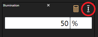
Number editor
Clicking on an editable number in the software brings up the number editor. Both the value and the unit of the current number can be changed. They only become effective once the number is applied.
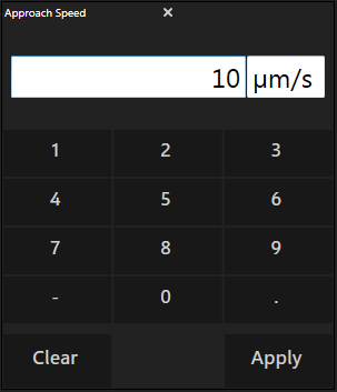
The number editor validates the input and gives feedback if, for example, the unit is not supported or the value is out of range.
Hint
You may use u instead of µ (e.g. um = µm).
If the slider icon is present, clicking on it shows a slider instead of buttons to set the desired value.
Hint: Scientific notation
The number editor also supports scientific notation. E.g. one can write 1e-6 instead of 0.000001.
Stage movement
Standard dragging
While looking at a sample, clicking and maintaining pressure on the mouse’s left button will trigger a dragging process. At that point, the cursor will change to a grabbing hand. The standard dragging is meant to be intuitive: click on an object on the sample and drag it to the center of the screen, for instance.
Infinity movement
While the standard drag is the ideal way to carry out small movements, the need to travel longer distances within a well might arise. To this end, use the so called “infinity” drag. Clicking and holding the mouse’s left button while hovering around the edge of the screen and will trigger a constant movement. The switch between standard dragging and “infinity” movement is seamless.
A screenshot of an “infinity” movement indicated by the white arrow over a transparent border.
Boundaries
To prevent the probe hitting a plate, a boundary checker is implemented for each plate type. As a result, a red transparent border appears whenever a boundary is reached while moving the stage, be it when dragging or in “infinity movement” mode.
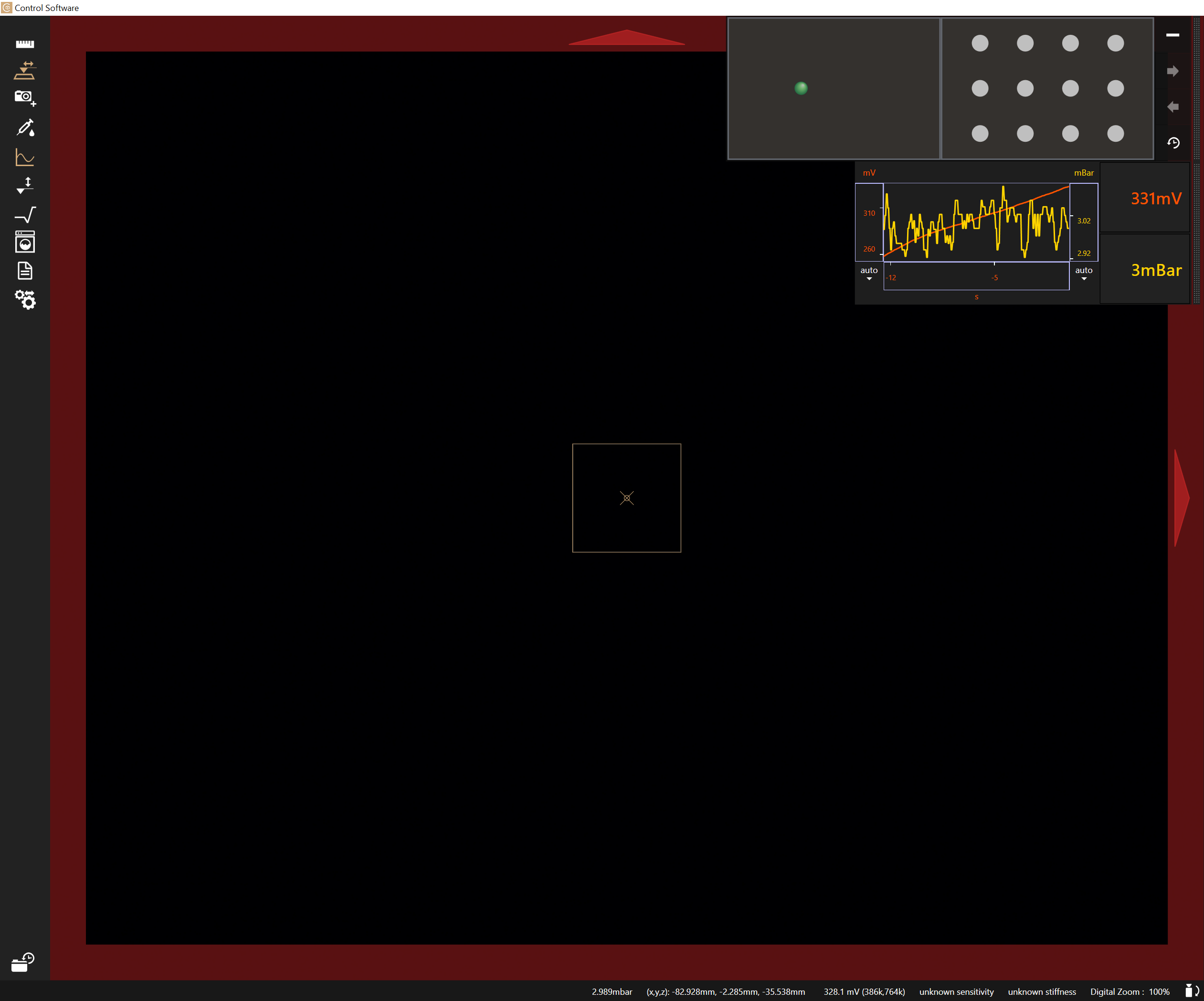
A screenshot of a boundary warning: the red arrows show the forbidden directions while the red, transparent border indicates a boundary was reached.
Settings
| Settings Name | Description | Persistent |
|---|---|---|
Approach Setpoint |
The probe deflection value at which the approach will be stopped. Typically around 10 mV or 30 nN. Higher values are sometimes necessary if noise is encountered due to floating particles in the sample. | No |
Approach Speed |
How fast the probe approaches the sample. Higher values can drastically reduce the time to approach, but also increase the risk of probe damage. We recommend values around 5 µm/s. | No |
Retract Speed |
The speed at which the probe is lifted away from the surface. | No |
Illumination |
The system has an integrated LED illumination. Set its value here. | Yes |
Objective |
Choose which objective is used. It is important to adjust this value manually whenever changing the objective. The magnification is an important information for CAPA to know the right scale. | No |
Show Help Lines |
Choose whether to show help lines (a crosshair and a square indicating the size of a 100 by 100 µm area) in the center of the video view. | Yes |
Idle Pressure |
The pressure that will be constantly applied by the pressure system in idle situations (preventing liquid from flowing through the cantilever in either direction). This value is automatically updated after probe filling. | Yes |