System Calibration
Important
Carefully read the entire chapter before starting the calibration.
The calibration should only be carried out by trained operators.
The system must be calibrated after being assembled to determine and compensate for mechanical tolerances. The software comes with calibration methods included which must be run before the system can be operated.
General prerequisites
- Ensure that all three axes can move to to their extreme positions.
- Ensure the head is mounted on the axis.
- Ensure the computer is connected to the controller.
- Power on the computer, the pressure controller and the system controller. Wait about 40 seconds until all components have booted.
- Start the software.
- Load the maintenance workflows, see the note below.
- Workflows should be run in the order they are listed in this document.
Note
The workflows described below are only available in Maintenance mode.
Open a console, such as Command Prompt, and type
cd "C:\Program Files\Exaddon\CAPA" && .\CAPA.exe /maintenance as a single
command to start the application in Maintenance mode.
Stage handling during calibration
Plates must be inserted or removed for certain workflows at a time at which the system is not fully configured yet. However, operating with an incompletely configured system bears the risk of probe crashes. The following methods are always available though:
- Plates can be removed or installed with the exchange plates workflow. Make sure to retract the Z stage in case the defined content height is lower than the actual plate borders.
- Inter-plate moves can be performed by configuring a plate as WellPlate
with really high
Content Level. One can then switch between the areas represented by wells without having to worry that the probe touches the plate.
In case of an unset Z-level most movement commands are either disabled or
return an E_INVALID_ARG error. The available Z range is however
displayed in a warning message during startup and enables the operator to
temporarily set an estimated Z level by adding 4mm to the lower bound and
save it to the configuration file as PlaceHolderLevel (see the note below
and the section Calibrate Z).
Configuration File
Some parameters can be adjusted in a configuration file located in:
C:\ProgramData\Exaddon\CAPA\settings.xml. This is intended for advanced
users only as all values can be set through the software as well.
Windows Administrator Rights are required to save this file after modification. This XML-formatted configuration file can be edited with any text editor such as Notepad. Make sure the software is not running when saving new values. Otherwise, changes to the file performed by the software might get overwritten or overwrite your changes when closing the software. Furthermore, the containing folder is not shown in Windows Explorer by default (hidden folder). This restriction can be bypassed by entering the full path to the file directly in e.g. notepad.
Stage Dragging
Stage dragging is allowed during the execution of most actions. Use with care. Incompletely configured systems might cause unexpected movements. Also, do not start a drag operation while another movement is pending.
Lens configuration
Ensure both cameras are installed.
-
Run the
Setup Lensesworkflow: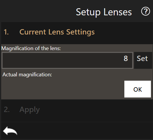
-
For the current active camera, enter the lens magnification in the dialog. Do not click
OKyet. Default magnification values are :- 8x for the bottom camera
- 3x for the top camera
-
Click the exchange camera button
 and enter the other camera magnification.
 - Apply the changes by clicking
OKtwice. - Restart the software to take the changes into account.
Bottom Camera Alignment
The bottom camera needs to be rotated in order to align the observed X/Y stage movements with horizontal and vertical axis of the screen. This is mandatory for dragging and direct interface between the displayed image and the real system positioning.
Prerequisites
- Bottom camera is installed.
- A plate with transparent material is installed that contains an small, identifiable object (e.g. a slightly dusty well plate or the 3DP calibration plate).
- Plate configuration is adjusted to match the plate chosen.
- Illumination is turned on.
Process
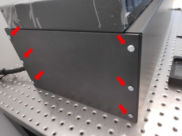
-
Unscrew and remove the side cover plate to access the bottom camera
-
Using the navigation tool, move over a transparent plate area.
- Run the
Align Cameraworkflow. The stage begins to repeatedly move along its x axis by +- 200um. -
Loosen one of the knobs maintaining the tubing in place until the camera can be rotated.
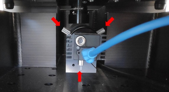
-
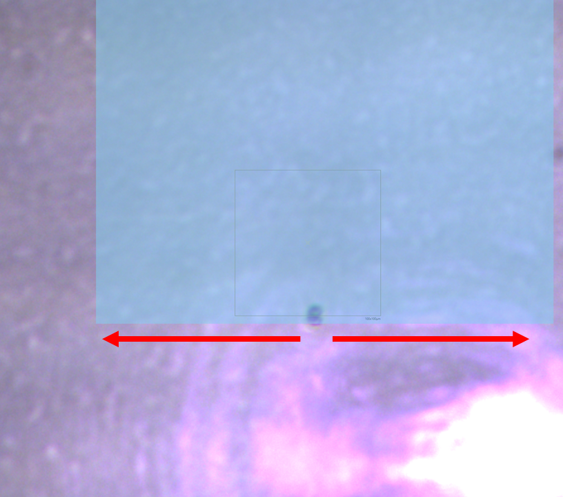
Focus on the plate and select a reference point (a previously drawn indicator, a piece of dust, etc.)
- Drag the overlaid, semi-transparent rectangle so its border appears above the reference point.
-
Rotate the camera until the reference point moves parallel to the border of the rectangle. Use the mouse wheel to increase the size of the rectangle for better accuracy.
-
Retighten the alignment knob. Make sure the camera did not rotate during tightening.
- Exit the workflow.
General Alignment
The camera must be aligned so that a cantilever’s chip is located at the bottom of the reported image frame. This might not be possible if the head has not been centered yet. If it turns out that the chip is located on the wrong side, one can adjust the alignment and run this step again.
Calibrate XY (Head)
This step is carried out in order to position the Z-Stage module according to a probe. By doing so it can be ensured that probes are centered on the screen and aligned with the bottom camera axis, needed for safe gripping and dropping of probes.
Prerequisites
- Bottom camera is aligned.
- Head is mounted.
- A probe is mounted.
- No plates are installed.
Note
A new probe is not needed: a old probe can be used for calibration purposes, as long as it is dry and has a complete and identifiable cantilever. It would even be preferred if sucessful gripping and printing have already been conducted with it, ensuring the probe can be trusted as a reference.
Process
- Remove all plates from the X-Y stage, if any.
- Run the
Calibrate XY (Head)workflow. - The probe moves to a predefined height.
-
Use the adjustment X-screws and Y-screws to align the probe’s tip with the overlaid mark at the center of the screen:
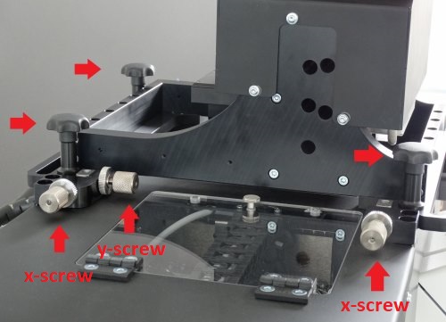
Proper calibration of the system requires the Z-stage to be aligned with the XY-stage. Always screw or unscrew both X-screws by the same amount to not induce rotation that would prevent proper gripping of the probes.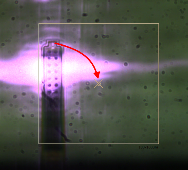
-
Fix the module’s position with the hand-tightening screws.
- Exit the workflow when the tip is centered and screws are tightened.
Note
When centering the probe with the adjustment XY-screws, one should pay attention to minimize the rotation of the head (move both X-screws by a similar distance).
Top Camera Alignment
Cameras need to be rotated in order to align the observed X/Y stage movements with the horizontal and vertical axis of the screen. This is mandatory for dragging and direct interface between the displayed image and the real system positioning.
Prerequisites
- Top camera is installed.
- A plate with transparent material is installed on the left port that contains an identifiable object at content height (e.g. a substrate with dust, structures or marks, or the alignment grid of the 3DP calibration plate).
- Plate configuration is adjusted to match the plate chosen.
- Top camera illumination is turned on.
- X-Y (Head) calibration is completed.
Process
Danger
Make sure the tip is retracted to the uppermost position before dragging the stages as long as the whole calibration routine is not yet completed to avoid any tip crashes. It is not advised to use the navigation tool to approach a surface as the Z axis is not yet calibrated and there are risks of tip crashes.
- Move the stage in order to see the surface at content height via the top view camera.
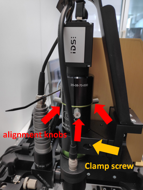
- Set the lens’s focusing current of the top camera to 0 mA.
-
Loosen the clamp screw and adjust the camera’s height to bring the sample or reference grid into focus. Retighten the screw once the camera is positioned.
-
Start the
Align Cameraworkflow. The stage begins to repeatedly move along its x axis by +- 200um. - Click the exchange camera button to go to top view, if needed.
- Loosen one alignment knob until the camera can be rotated.
- Repeat steps 6. to 10. from the bottom camera alignment procedure to align the observed movement with the horizontal axis of the screen.
Calibrate XY (Stage)
The purpose of this step is to determine the coordinate of a known reference point on the mounted stage with respect to the image’s frame of reference. In other terms, it is equivalent to align the bottom camera in the coordinates of the XY stage. The reference point used is a small hole in the 3DP Calibration Plate that can be identified easily on the screen.
Prerequisites
- Camera is aligned.
- Head is mounted and centered.
- A probe is mounted.
- The 3DP Calibration Plate with the reference hole is installed on the left port, pushed to its top-most and left-most position.
- Illumination is set to 100%.
Note
The calibration plate can move slightly in the port. To get consistent measurements of offsets, it is advised as a convention to always place it so that it is pushed to its most top-left position in the left port.
Process
- Start the
Calibrate XY (Stage)workflow. -
Click on the appropriate reference position
3D RefPos. The axes move close to the reference hole position.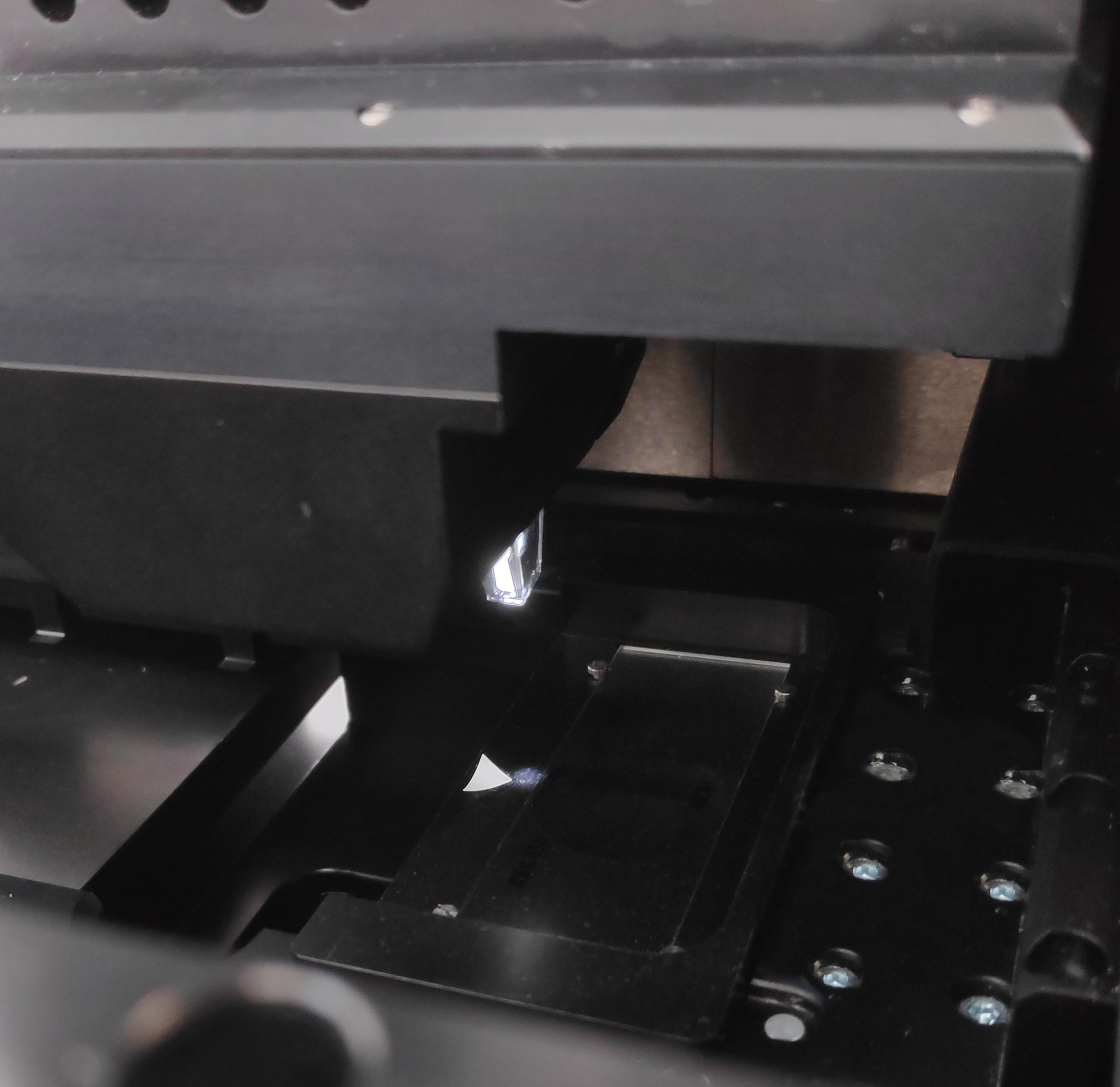
-
Search for the hole in the plate. Use direct observation of the stage and spotlight position as guides until the hole appears on the screen.
-
Focus on the surface to get a circle as clear as possible.
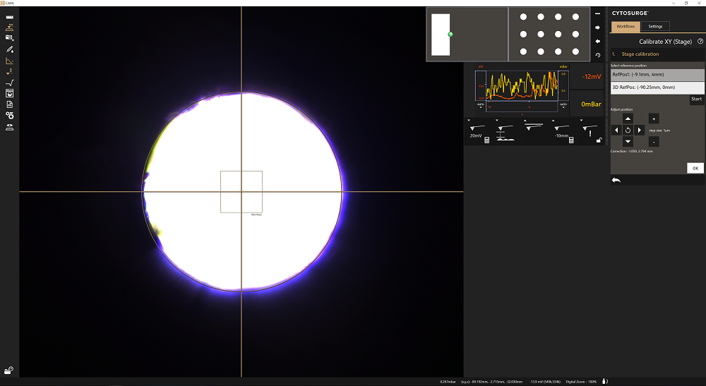
-
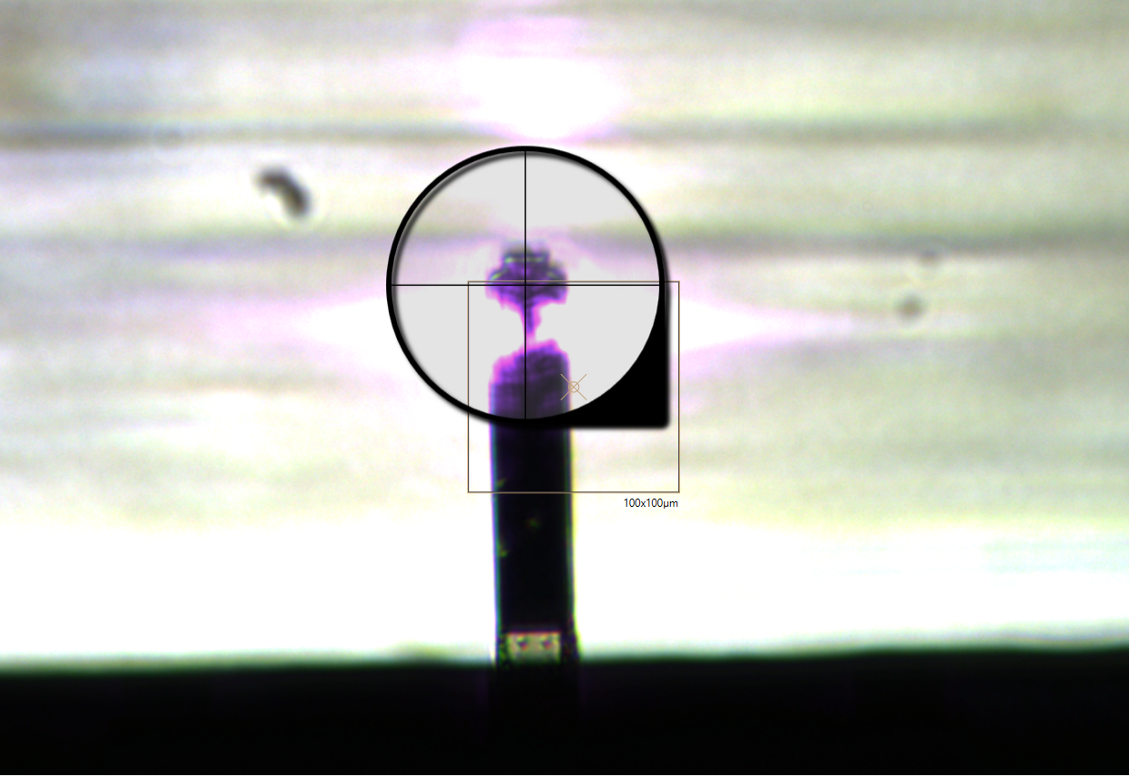
Use the arrow navigation to center the hole on the screen, using the vertical/horizontal lines and the reference circle as guides. Use the mouse wheel to adjust the circle on the hole’s edges.
- Click
OKand confirm that you want to apply the new offset. - Restart the software to use the updated values.
Note
If the camera is not sensitive enough to show the structure as pictured
above, manually modify video settings like the exposure and gain values of
the software located in the View section of the Settings tab.
Calibrate Z (Height)
This step is carried out to determine the exact height of the probe holder.
Prerequisites
- Head and stage (XY) have been calibrated.
- At least one probe holder plate is installed. Calibration can only be performed on empty slots!
- A probe is mounted.
Process:
- Run the
Calibrate Z (Height)workflow. -
Select the probe holder slot(s) at which the Z height will be measured.
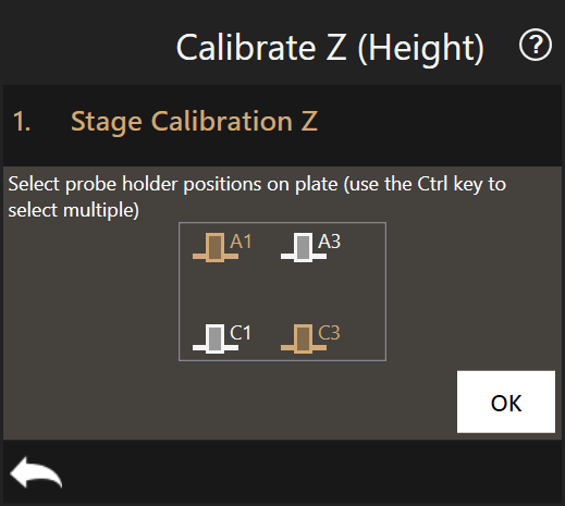
-
For each selected slot:
- (Automatic) The Z-axis retracts.
- (Automatic) The head is moved above the selected slot.
-
(Manual) Carefully lower the head in Z-direction until the consumable slides in the slot and the head touches the probe holder plate. Use as little force as possible. Repeat this 3 times to ensure the value is stable.
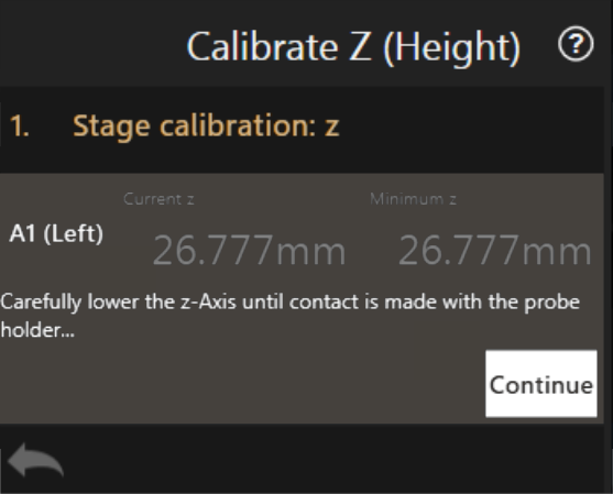
-
(Automatic) The minimum Z position reached is saved.
-
Press Continue to move to next slot.
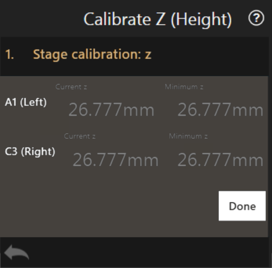
-
Press
Doneand confirm that you want to save the new plate holder level. - Restart the software to use the updated value.
Note
The software subtracts 14.47mm from the measured average minimum height. Subtracting 14.47mm comes from adding up the 3DP probe holder level, how much the consumable sticks out and the height of the o-ring.
-14.47mm = -35.54mm (3DP holder level) + 20.94mm (consumable sticking out) + 0.13mm (o-ring height)
Calibrate Pixel Size
This step measures and configures the actual magnification as displayed in the software. It might differ slightly from the rated value reported by the objectives due to various factors. It is important to determine the effective magnification as otherwise, digitally overlaid content doesn’t appear scaled correctly or selected points (e.g. with crosshair) have small offsets.
Prerequisites
- Camera is installed and aligned.
- A transparent plate is installed with marks, some dust or a reference grid.
Process
- Run the
Calibrate Pixel Sizeworkflow. - The menu displays the currently available objectives. Note that the already calibrated objectives are displayed with their corrected magnification.
-
For each objective:
-
Select it in the list to start the calibration and click
Continue.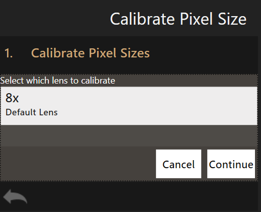
-
Focus on the plate and select a reference point which will be used as reference coordinates (an existing feature, a piece of dust, etc.).
- Configure the two offsets, (ax, ay) and (bx,by), according to which the stage will be moved. Choose the distance close enough so the reference point will still be visible in the field of view but are appart enough to get a precise measurement (e.g. 400 µm for bottom camera or 800um for top camera). Then click
Continue. - The first offset (ax, ay) is applied. Select the reference point with the crosshair to measure the distance traveled. Click
Continue. - The second offset (bx,by) is applied. Select the reference point again with the crosshair to measure the second distance traveled. Click
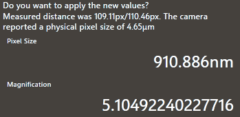
Continue. -
The measured magnification is computed and displayed. Below is an example of the effective magnification of a 5x objective. The value can be edited by clicking on the magnification value.
-
-
Repeat step 3. for every installed objective.
- Restart the software to apply the new calibration values.
Measure Top Camera Offset
Like the bottom camera is aligned with the stage coordinates during the Calibrate XY (Stage) step, the top camera positioning must be corrected to match the stage coordinates for the pinpoint positioning of structures during the 3D printing process.
Prerequisites
- Top camera is aligned
- All axes are calibrated
Process
- Load the 3DP Calibration Plate on the left port.
- Move the stage to the calibration plate center and focus the bottom camera view on a mark easily distinguishable from the rest of the plate.
- Run the
Measure Top Camera Offsetworkflow. -
Center the mark chosen as a reference point for the offset measurement under the crosshair, then click
OK.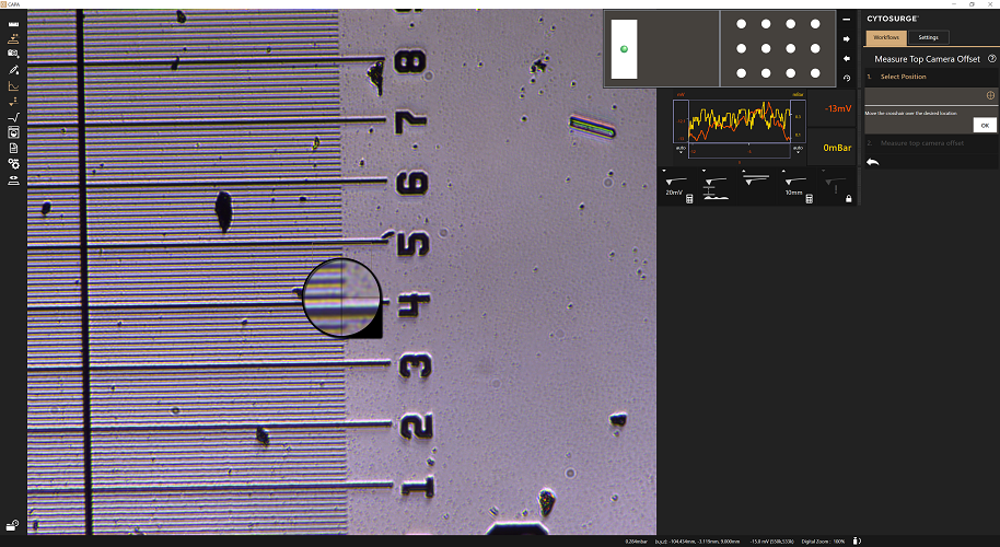
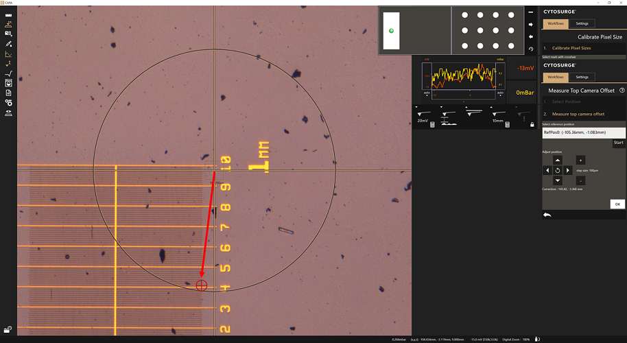
-
The bottom view changes for the top view and the stage goes to the supposed coordinates of the reference point in the top camera’s frame of reference.
-
Use the arrow navigation to center the reference point on the screen, using the vertical/horizontal lines and the reference circle as guides. The mouse wheel can be used to adjust the circle diameter to the mark’s edges.
-
Click
OKand confirm that you want to apply the new offset. - Restart the software to apply the changes.
Calibrate XY (Stage) - fine tuning
Some offsets can stay uncompensated in the system. In some cases, they can add up in a non-negligible offset. This last step is a check to reduce those remaining uncertainties.
Prerequisites
- Bottom camera is aligned
- XY (Stage) is calibrated
- XY (Head) is calibrated
- Z height is calibrated
- Pixel size is calibrated
- A probe holder plate is installed
- A probe is mounted
Process
- Run the
Calibrate XY (Stage) (fine)workflow. - Drop the gripped probe.
- Refer to the Choose Probe workflow on how to drop and grip probes as the action used in this workflow is the same.
- Measure the offset between the tip of the cantilever and the center of the screen by selecting the tip of the
cantilever with the crosshair.
- Click
OKand confirm that you want to apply the new value. - Restart the software to apply the changes.
Calibrate Alignment Motor
Process
- Run the
Calibrate Alignment Motorworkflow. - Select the motor type to be calibrated.
- Adjust the calibration position if required. The default values, updated when the motor type is set, are usually fine.
- Run the action by pressing
OK. - Repeat for every motor type.
Note
The calibration (frequency tuning) is ideally performed when the head is running at its operating temperature. This state is reached after one hour.
Recover probe loss during the calibration process
The system must not be operated without a probe attached. If the probe gets lost and the system configuration is not yet complete, one must not try to grip a new probe with the gripping workflow as there exists a high risk of damaging hardware components.
Instead, following procedure must be applied:
- Turn off the controller.
- (optional) Remove the head cover.
- Remove the data/power cable and the pressure cable and detach the head from the axis.
- Ensure a probe is ready to be mounted.
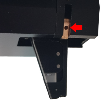
-
Manually open the grippers by inserting a lever into the gripper’s hole (see image below) and pushing it up. Install the probe and let the grippers close again. Ensure the sealing screw enters the probe reservoir and does not rest on the reservoir’s border.
-
Fix the head onto the axis, connect the cables and add the cover.
-
Some calibration steps must be performed again as the head was moved
Calibrate XY (Head)Calibrate Z (Height)Align Camerafor the top cameraMeasure Top Camera Offset