System preparation
The air tightness test reports an error
After the probe has been gripped, the system automatically performs an air tightness test. It applies 20mbar and measures the average flow. If the absolute flow is greater than 0.10Pa, a warning is displayed:
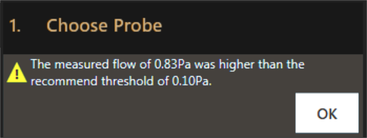
This means that the probe has not been gripped correctly and it is not in the correct position on the head. The most common cause for this is a contamination of the head nose: the ioninks can leave deposits on the head nose that accumulate over time.
Gripping is a delicate operation. There are several reasons for a failed gripping:
- The head nose is contaminated (most common)
- The probe is not correctly placed in the probe holder plate
- The probe holder plate is not placed correctly on the sled
- The system is not correctly calibrated
How to spot that the probe was not gripped correctly
- The cantilever appeared poorly centered after gripping (further than ~100 µm away from the center)
- An axis disengaged during gripping
- The software reported an
I2C error
What to do
- Repeat the procedure from a different port
- Check that the probe holder plate is correctly installed in the sled. There should be no wobble when pressing on it
- Remove the probe and try with a new one
- If the problem persists, clean the head nose
- If the problem persists, inspect the head. Contact support for assistance
- If the problem persists, try to recalibrate the system. Contact support for assistance
Temporary fix to avoid probe loss
If the problem cannot be immediately solved, the manual proble adjustment procedure can be performed. This is intended as a temporary fix to avoid the loss of the iontip. If the problem persists please perform all the necessary steps for troubleshooting.
Manual probe adjustment procedure
Important
This is a delicate operation and should only be performed in exceptional cases and by trained personnel.
If the probe cannot pass the leak test after multiple attempts, manual probe adjustment can be performed. This allows the probe to sit correctly on the print head with the aid of a manual adjustment. To perform the operation:
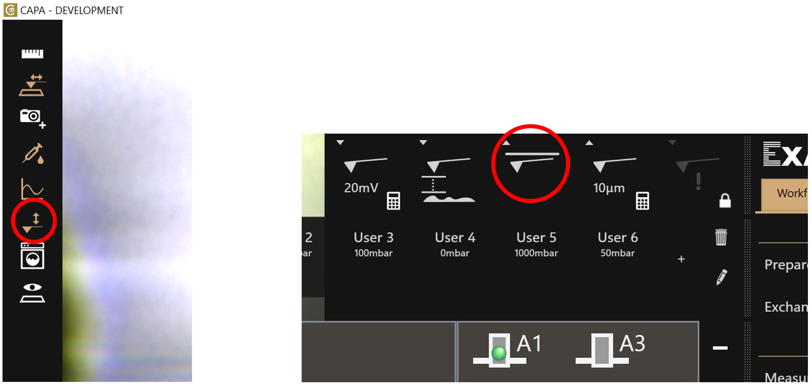
- Raise the head to home position using the Probe Tool
- Manually adjust the probe on the head with your hand. Wiggle it and rotate it gently. In most cases you will hear an audible “click”.
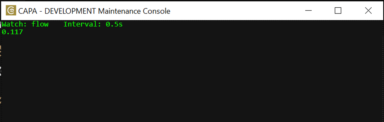
- To check the tightness, open the CAPA console (
CTRL+SHIFT+C) and typewatch -n 0.5 flow paand monitor the value for 10 seconds. The values should oscillate between positive and negative and be lower or equal to 0.5 Pa. To close the measurement pressCTRL+C.
- To proceed with the workflow, you need to fill the probe. It is essential to fill the probe in air. To achieve this, load a well plate and move the tip to an empty well.
Risk of tip loss
Moving the tip to a well filled with water will result in tip loss.
- You can now proceed with the workflow normally.
Probe is not dropped correctly
Possible reasons for a probe not dropping are:
- The probe was dropped in an already used slot.
- The system was not properly calibrated.
- The O-ring and screw are dirty.
- The probe dried out after a long period of time and is stuck to the screw.
What to do
- Try dropping in a different slot
- Remove the head an manually remove the probe. Perform head nose cleaning workflow
Warning
Do not apply pressure during the dropping procedure. There is the risk of staining the prism and O-ring if there is ink in the reservoir.
Probe cannot be filled
It can take up to 1 min at 500 mbar to fill. Most common causes for a failed filling are:
- The reservoir contains bubbles
- The ink was not prepared correctly. Refer to this page for guidelines
- The probe is defective (warranty case)
What to do
- Increase the fill pressure
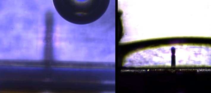
- Check for flow. Compare the deflection signal with the applied pressure as shown below
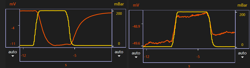 Left: normal flow. Right: clogged tip.
- If several tips in a row fail to fill, check for bubbles in the reservoir after filling it
Poor laser signal
Possible reasons for a poor laser signal are:
- The laser is not aligned properly.
- An air bubble formed after the probe was dipped into liquid.
- The laser window, the prism or the reflective coating of the cantilever are dirty.
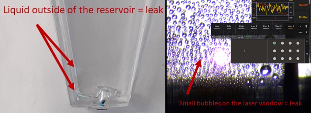
- The ink leaked from the inside
What to do
- Re-align the laser. The optimum place is about the ⅔ to ¾ of the cantilever length.
- In order to remove the bubble, the probe must be dropped and 15-30 µl of liquid has to be pipetted into the outer channel to remove all possible air. Please make sure a droplet always stays around the tip and pick the probe quickly as the cantilever must not dry out.
- Unmount the head to check for prism stains and Clean the prism
- If the ink has leaked from the inside, drop the probe in the probe plate and wait 2 minutes. Grip the probe again and continue the workflow.