Design Rules
Design rules are guidelines giving an overview of the capabilities and limitations of the system.
Important
Not following those rules might leads to:
- Accelerated wear of the consumable.
- Tip breaking or clogging.
- Crushed or bent printed structure.
- Inconsistency and unreliability of the tip calibration.
- Decreased efficiency and speed of the printing process.
- Decreased resolution and quality of the printed structures.
Printing chamber and printing area
The shape of the consumable and the printing chamber result in a limited reachable area. Printing chambers specifications about the usable samples and reachable area are found here. To use a larger area or specific samples, a custom printing chamber must be built and its plate definition has to be added to the printer.
Printing chamber V3
| Parameters | Range | |
|---|---|---|
| Allowed substrate size | Small substrates | Large substrates |
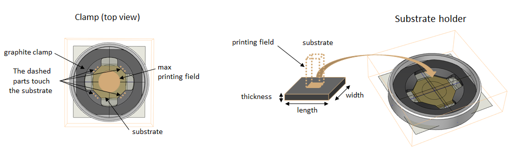
| Length (mm) | 14.6 - 15.3 | 24 - 25 |
| Width (mm) | 14.6 - 15.3 | 24 - 25 |
| Thickness (mm) | 0.3 - 3.4 | 0.3 - 3.4 |
| Printing field size (X-Y-Z) | Ø ~ 8 mm | Ø ~ 16mm |
The clamp sits on top of the substrate holder and mechanically pushes the substrate down. The clamp also makes electrical contact as it is made of conductive graphite that is pushing on the substrate at four positions indicated by arrows.
Process limits
To ease the design process or to know if a given structure would be printable, key points and limit values are shown here.
Voxel limitations
The printer has a limited reservoir capacity of 1 µl. The first parameter to estimate is the material volume needed to print a given object. For copper printing, this will result in the first figure below.
The other key parameters are the voxel size and height since they give the resolution of the final structure and the number of voxels after generating the printfile (scripting or slicing). A smaller voxel will result in thinner and sharper edges but also longer printing times.
All values should be in the accessible range.
Note
For all subsequent figures, all values in green can be accessed under normal circumstances. Values in orange only can be obtained under certain circumstances.
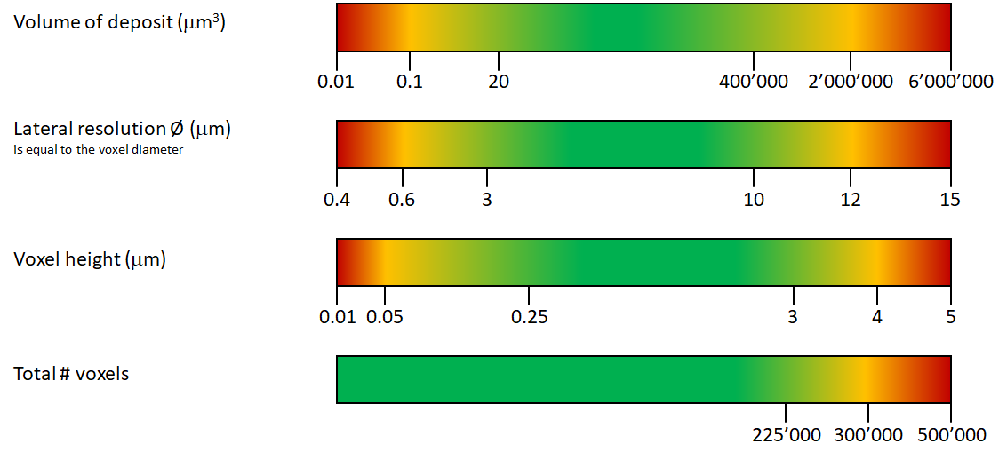
The total number of voxels a tip can print is equivalent to its lifetime and vary from tip to tip due to manufacturing inaccuracies but also to its usage. The safer the printing conditions are, the longer the tip can reliably print. Negative voxel deflections (copper growing around or inside the tip) or large positive deflections (collisions) tend to greatly reduce the lifetime of a tip.
The voxel height is linked to the pressure and diffusivity of the deposited ions or particle: the further the surface is from the aperture, the slower the deposition because of diffusion and transport limitations.
To use a high voxel height, the pressure must be increased keep the same deposition speed. A high voxel height will also decrease the resolution but reduce the voxel count in a structure.
At low voxel height, a structure growing faster than the average speed of the printer creates collisions, breaking or clogging the tip. Therefore, the pressure must be reduced to limit the growing speed and the volumetric printing speed of the material. Low voxel heights increase resolution at the expense of higher voxel counts and slower printing speed.
Note
If a structure happens to be too large to be printed, trade-offs can be made to reduce the volume and time of printing:
- Consider printing empty shells or filled with lattices instead of solid volumes.
- Mix pressures to use larger voxels where a high resolution is not needed to reduce the number of voxels.
Printing time
This figure can be used to get an idea of the time needed to print any structure by selecting the number of voxels printed per second. The printing time has an upper limit as the supporting electrolyte slowly evaporates in a non-controlled atmosphere. Printing sessions longer than 24 hours are not recommended.
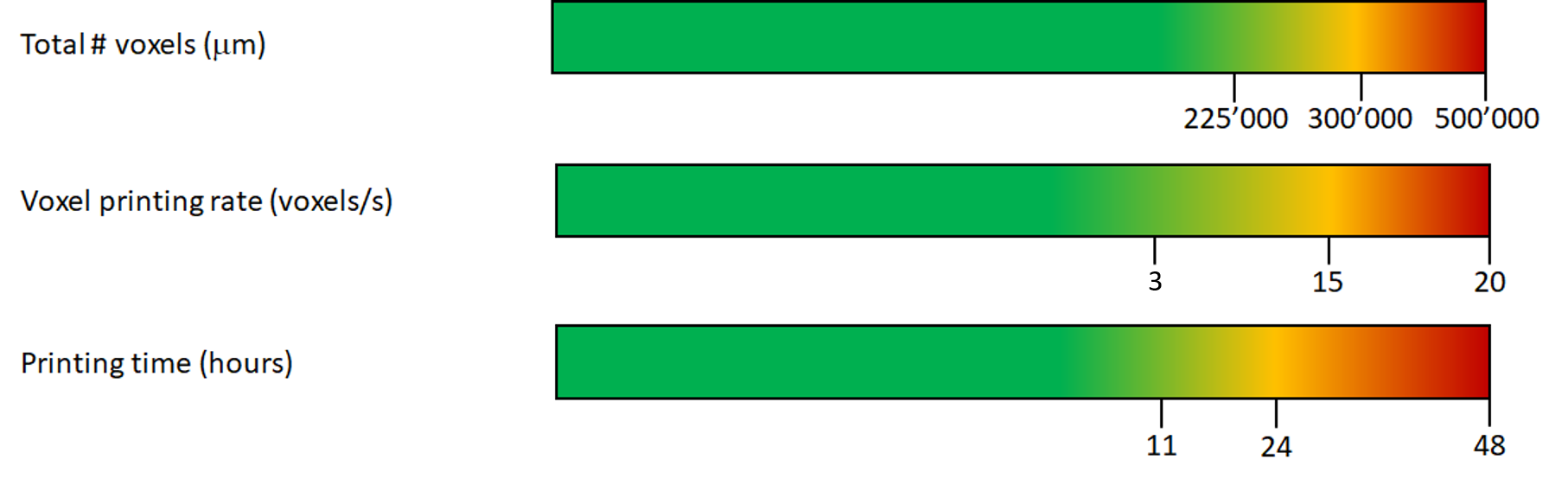
For reference with the printing chamber V3 and standard Cu printing solution, the saturation plating speed (see below) drifts at a rate of +0.05µm/s per hour, impacting the quality of the print over time.
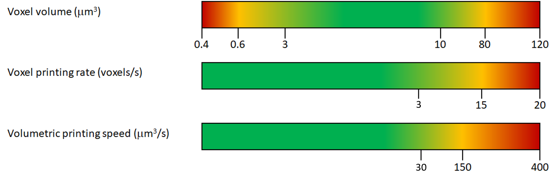
Throughput
Knowing the diameter (lateral resolution) and height of a voxel results in an average cylindrical volume filled by each of them. With the targeted voxel per second, the theoretical volumetric printing speed needed (and therefore, the dispensing pressure) can be known.
Copper printing rate
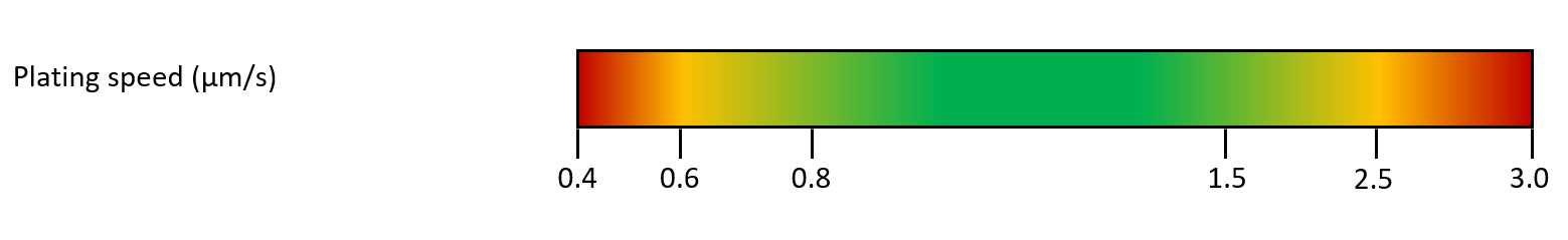
The next figure is specific to the copper printing case and gives the reachable printing rate in µm/s (measured along the Z axis). For example, a voxel of 0.5µm height printed at 1µm/s takes 0.5s to complete. The tip calibration app will help to match the lateral resolution (voxel diameter) wanted, the voxel height and the voxel printing rate by tuning pressure and potential.
Rates between 0.8-1.5 µm/s are preferred for quality results.
Higher values lead to merging and smoothness issues but faster prints. Lower values give better printing performance but a lower object definition.
To know what value to target in the tip calibration app, first find the printing rate needed:
Warning
This calculation is a good estimation for single, 1D strands. For closely packed strands (spirals), 2D and 3D structures, effective diameter and printing rate (µm/s) are underestimated by the calibration. This is due to a spray effect linked with diffusion and transport of ions away. They deposit away from the tip on previously printed surfaces (diameter increases) and will reduce the space left to print for the next layer of voxels (increased effective printing rate). This effect is dependent on the geometry and routing of a structure. Test prints should be conducted to reduce the pressure in those cases.
Designing a printfile
Building solid objects from a growing metal surface can be achieved in a variety of ways. However, not all of these result in high quality and reproducible printed structures.
The most effective way to create a three dimensional object is to fill the volume with a continous strand of metal. For example, when building a wall one should build a series of horizontal lines stacked on top of each other, as shown below.
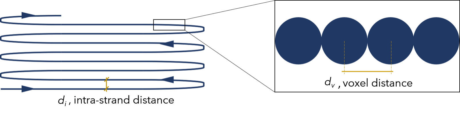
In this way, the metal grows primarily from the voxel that was just printed rather then from the metal of the strand below the tip. In order to favour the growth of the metal in this fashion one needs to select proper values for the intra-strand distance, di, and the voxel distance, dv.
Standard values for printing speed, s, voxel distance, dv, and intra-strand distance, di, are shown in the table below. Each set of values is dictated by the selected printing quality (smooth, balanced, coarse).
| Quality | s [µm/s] | dv [µm] | di [µm] |
|---|---|---|---|
| Smooth | 1 | 0.5 | 2 |
| Balanced | 1.5 | 1 | 2 |
| Coarse | 2 | 1.5 | 3 |
Routing
Once the structure parameters are defined, the routing of the voxels inside the structure itself must be setup. The printing order of the voxels is crucial to obtain good and reliable results.
Three routings are possible for a given structure design:
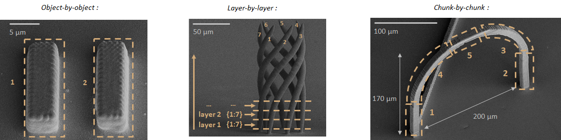
- Object-by-object, where each element of the design is printed individually.
- Layer-by-layer, where each layer of voxels of the same Z level are printed one after each other, building all objects at the same time.
- Chunk-by-chunk, where blocks (or chunks) of the structure are printed one after each other taking into account the clearance rules to define the size and order of the chunks. This must be implemented manually in the generated printfile or script. It has the advantage to greatly reduce the movement in-between voxels and spare printing time but will likely create seams at each junction.
As the cantilever and consumable have a footprint over the substrate, trying to print a voxel lower than voxels already printed will very likely lead to a collision between the consumable and the structure. The same clearance rules apply as for the substrate placement below.
The VCG will assemble objects in a single design with an object-by-object routing by default. It has an inbuilt function to check for collisions within the design and options to reroute layer-by-layer (safest) or to auto correct collisions in an approach close to a chunk-by-chunk routing.
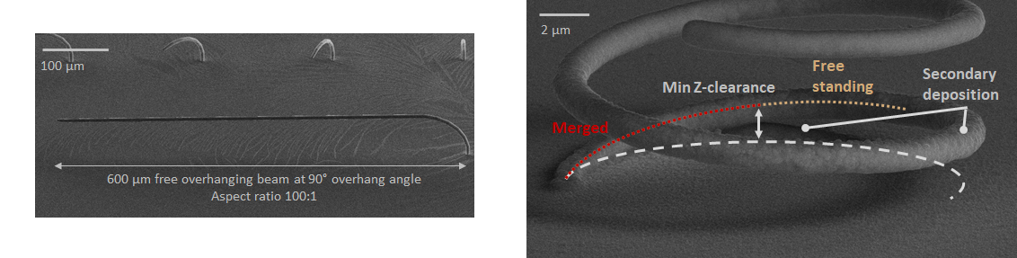
Overhangs and free-standing structures design
The system can print overhanging structure and free-standing structures with little to no additional supports needed due to the scale of the printed objects and the liquid medium. The table below gives the average values related to overhangs. Limit length of overhang structures is defined by the spring constant of the free-standing structure being printed. As the voxel detection is made upon contact between the tip and the structure, the structure must be stiff enough to not prolongate the contact time: copper would otherwise have enough time to grow in the aperture and bind the tip to the structure, damaging the tip after retraction.
| Parameters | Range |
|---|---|
| Maximum overhang angle (°) | 90-100 |
| Safe overhanging beam length (µm) | 150 or less |
| Maximum length (µm) | 600 |
| Minimum Z clearance | ~ 1*voxel diameter |
The minimum Z clearance refers to the distance needed to create a free-standing beam above any surface: it should be at least equal to 1 voxel diameter (lateral resolution) defined above.
Spray
The secondary deposition also called “spray”, happens on surfaces around a printed structure depending on the printing conditions. Spray increases the final diameter of a voxel, help to smooth the surface or, in some cases, lower the surface quality. Spray is created by the deposition of copper ions diffusing away from the tip. Spray intensity and radius scale mainly with the pressure applied.
If the spray effect is too strong for a given geometry, it can be compensated by reducing their printing pressure, and therefore the base diameter of the voxels affected.
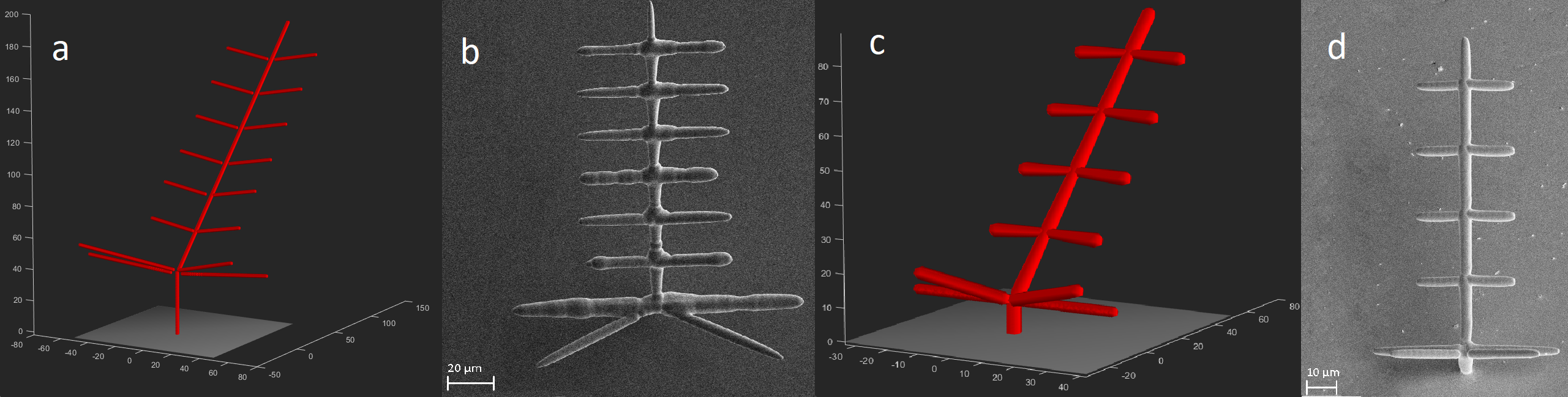
On the example below (a), spray deforms the structure at the joins and the long horizontal beams (b). This effect can be compensated by modulating the pressure ©. The resulting structure is more regular after printing (d).
Placing the structure on the substrate
To safely place printfiles on the substrate one needs to consider the shape of the iontip. This shape can cause collisions with structures which are already present on the substrate. As a general rule, always print in a left to right, top to bottom order to maximise the available clearance under the iontip.
In order to aid the placement of tall structures, please take into account the safe heights indicated in the following tables
Clearance over the whole substrate (excl. cantilever)
| Printing direction | Safe height [µm] | Limiting factor |
|---|---|---|
| Anywhere | 35 | Chip behind cantilever |
| Sideways (along ± X) | 100 | Plastic knobs |
| Downwards (along - Y) | 100 | Chip |
Clearance for a single line of structures (excl. cantilever)
| Printing direction | Interval [µm] | Safe height [µm] | Limiting factor |
|---|---|---|---|
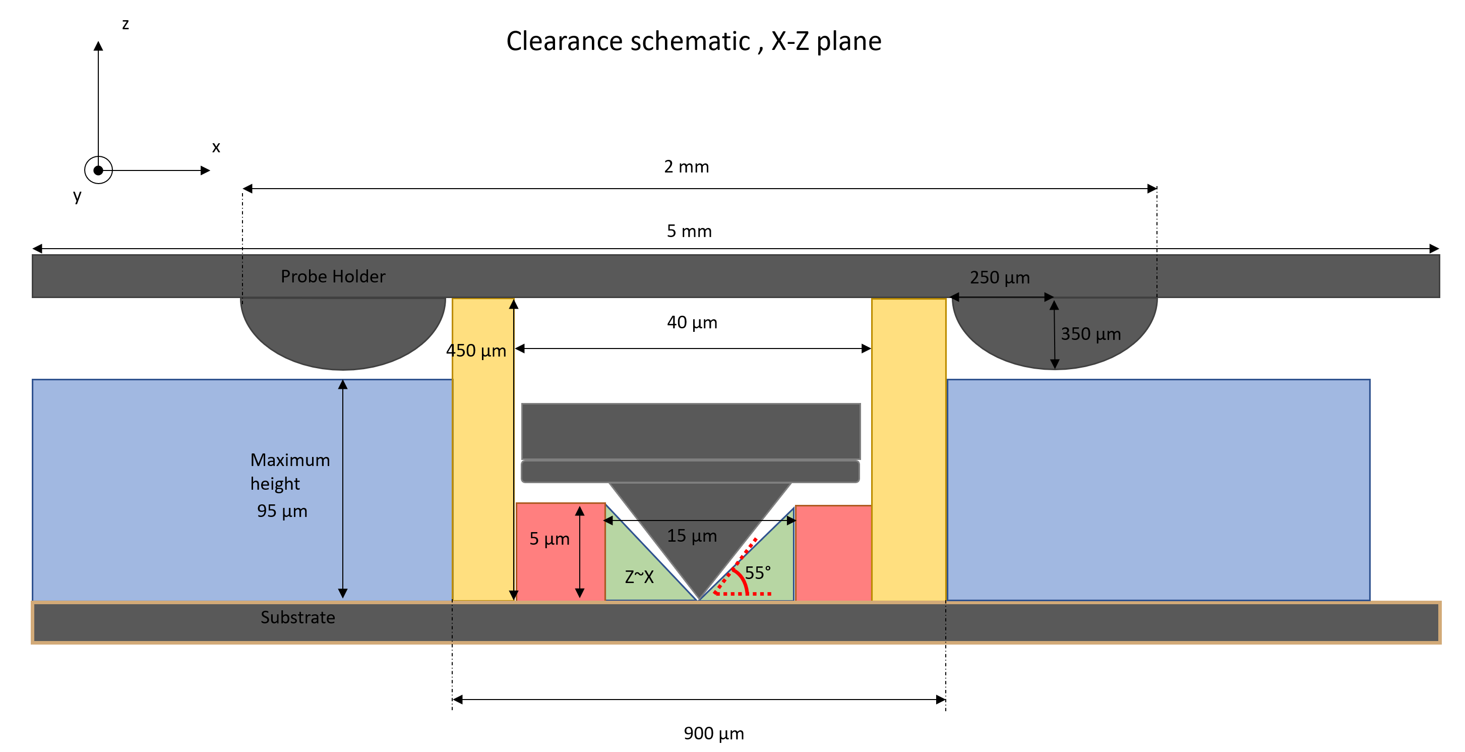
| Sideways (along ± X) | abs(X) < 500, abs(X) > 1000 | 500 | Plastic consumable |
| Sideways (along ± X) | 500 < abs(X) < 1000 | 95 | Plastic knobs |
| Upwards (along + Y) | all | 35 | Chip |
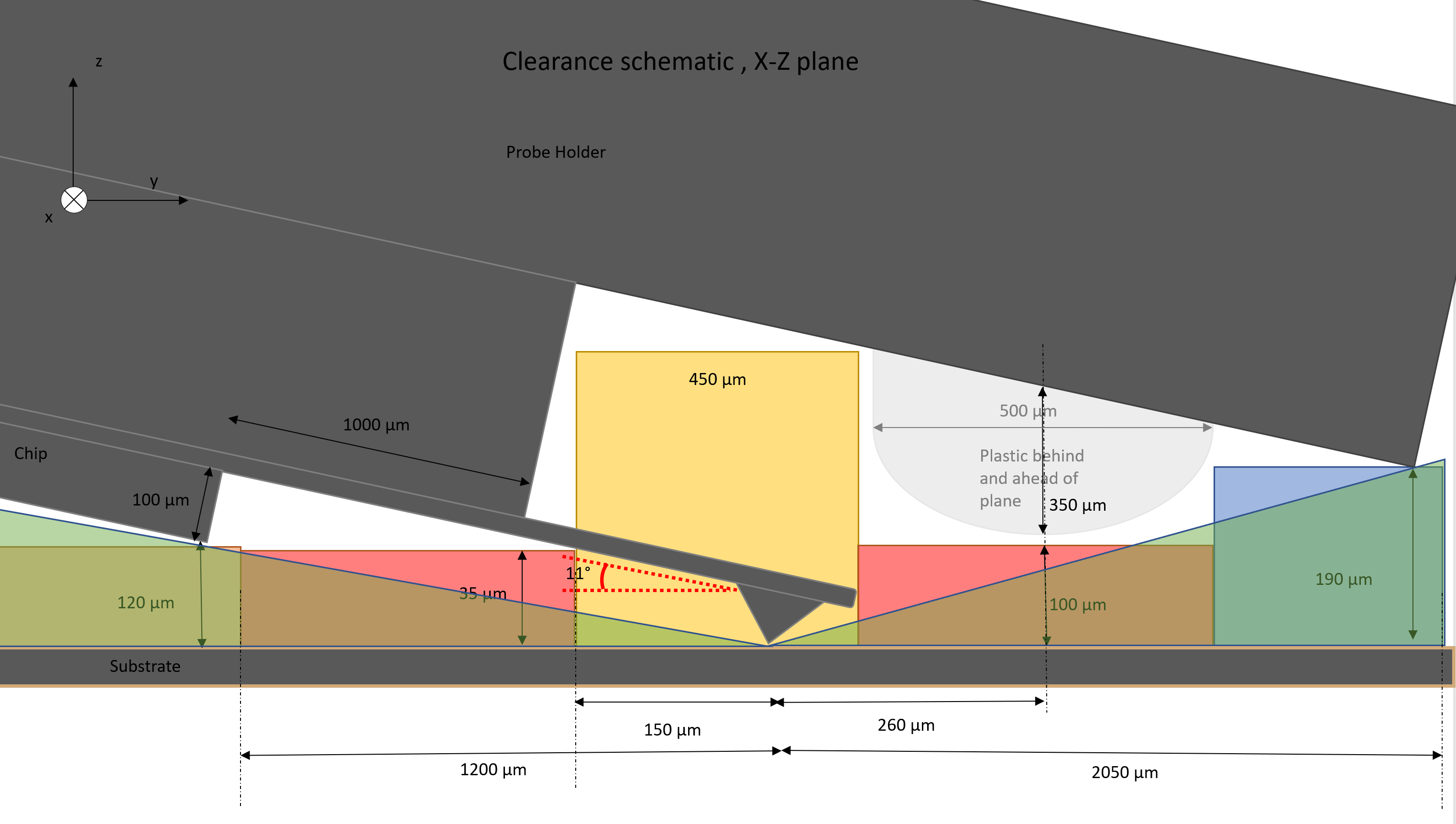
| Downwards (along - Y) | 1 < Y < 2000 | 450 to 190 | Sloping plastic consumable |
To better visualize where the limits indicated in the tebles stem from, please refer to the following shcematics. Additionally, you can toggle a collision check in the VCG.
Maximum structure height
The physical limitation to the height of a print structure is very high, it is given by the range of z stage from the printing substrate upwards (typically > 25 mm).
Warning
There is risk of damaging a previously printed high structure when moving the iontip into the printing chamber after printing a tall structure. To avoid this, observe the clearance rules above and set the content height of the printing chamber (see the exchange plates workflow) higher than the height of any structure on the substrate. The VCG assumes that the content height is set correctly and does not detect this kind of collision.