Mapping
This workflow is intended to measure the substrate’s local height using the system like an AFM in contact mode. Its main application is to derive the X and Y tilts of the substrate. From this set of measures, one can compensate the offset they induce which can become significant far enough from the approach point.
Deviations of the substrate from the horizontal plane induce a local height Z(X,Y)substrate different from the Z(0,0)substrate = 0 height set at the approach point. If this deviation becomes larger than a voxel height, the tip would approach a position below the substrate level, resulting in collision with high deflection and risks of breaking or clogging the tip.
When this deviation Z(X,Y)substrate is too negative, the voxel position becomes too far from the sample to grow. Either the print times out or the voxel grows from a neighboring voxel, creating detrimental free standing parts. This correction is especially advised when printing structures with a large footprint (>100um along X or Y) to avoid such detrimental effects.
1. Mapping in a nutshell
Mapping uses the absolute coordinates from the XYZ axes. In any camera’s view, the measurement is centered around the absolute coordinate of the target point, modulo the relevant alignment offsets (top/bottom camera calibration, 3D printing calibration and probe alignment).
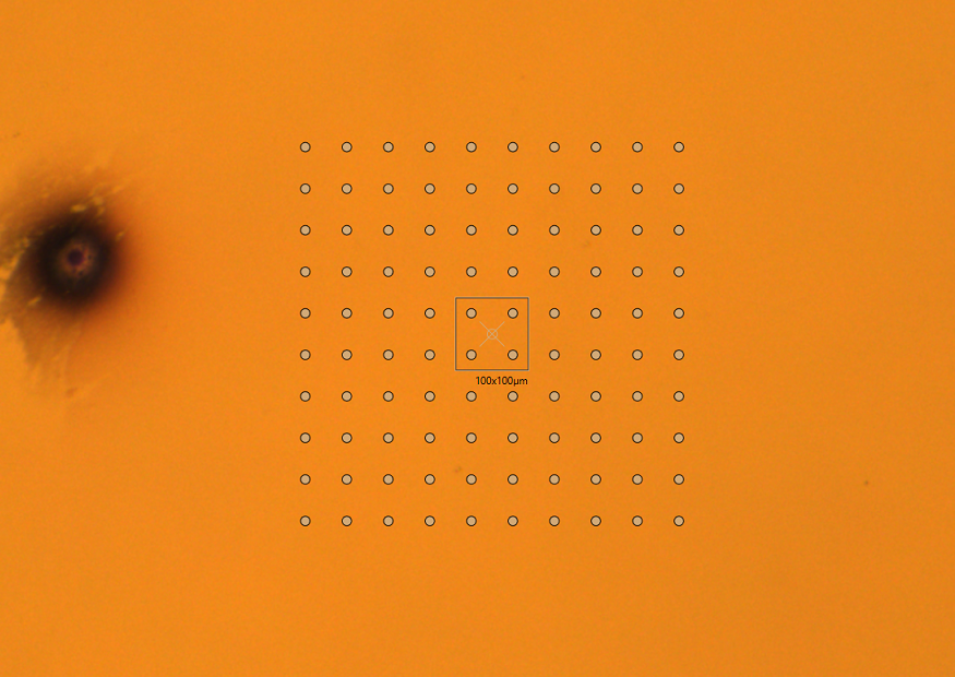
Points will be measured from bottom left to top right and a file with the
absolute coordinates measured at each contact point will be created in the
%USERPROFILE%\Documents\Exaddon\Substrate Maps subfolder.
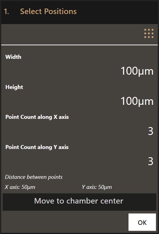
First the positioning parameters are entered:
- Width and height of the area to scan
- Number of measurement points along the X axis
- Number of measurement points along the Y axis
Clicking Move to chamber center moves the top view to the center of the
printing chamber which usually corresponds to the center of the substrate.
Move the grid of points above the area to map using dragging and/or the
navigation tool. Click OK to set the mapping parameters.
The mapping parameters are similar to the parameters used for 3D printing. The
same mechanism is used to map but without dispensing any liquid. Set the right
mapping parameters and click Map to start mapping.
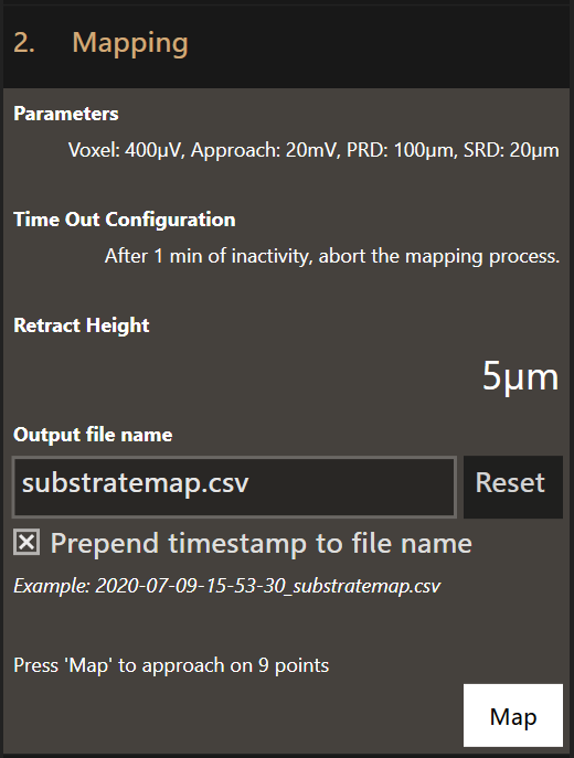
Once completed, use the Voxel Cloud Generator to analyze and compensate for the tilts in the subsequent printed structures.
Optional
- Time Out Configuration
- If the mapping process comes to a halt, the system waits this specified amount of time before aborting.
- Retract Height
- The retract height is the distance to retract after the setpoint of a point has been reached. Depending on the area to map, higher retract heights might be necessary to avoid crashing the tip.
- Output file name
- Specify a custom file name for the result of the mapping workflow.
2. Parameters
Clicking on Parameters will open the Mapping Configuration dialog where the
mapping parameters can be set. The default values are loaded every time the
software is started.
This is the Mapping Configuration dialog:
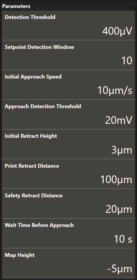
- Detection Threshold
- The cantilever deflection setpoint that defines point completion. The setpoint is relative.
- Setpoint Detection Window
- The amount of sample points used for threshold detection of the cantilever deflection signal. The first sample of the window is subtracted from the last sample of the window. If the result exceeds the detection threshold, a point completed event is triggered.
- Initial Approach Speed
- The approach speed of the cantilever at the start of the printing run. Maximum recommended speed is 20 µm/s.
- Approach Detection Threshold
- The cantilever deflection setpoint in Volts that has to be reached when the system first approaches the sample before printing. The tip will approach the sample at (X0, Y0). If the Approach Detection Threshold has been reached, the software defines the current z-position as Z0.
- Initial Retract Height
- After the tip has reached the substrate surface at (X0, Y0, Z0) it retracts the distance specified here and continues to the first point location at (X1, Y1) travelling at the defined height above the substrate surface.
- Print Retract Distance
- To avoid collisions when moving from one print structure to the next one, this distance is added to the currently defined content height when moving to the start position of the next print structure.
- Safety Retract Distance
- The distance to retract after a print structure has been printed. This helps to mitigate collisions with already printed structures.
- Wait Time Before Approach
- The time to wait after 0 mbar has been applied but before the approach starts. This prevents false deflection detections as the tip might still oscillate during the approach if no wait time is used.
- Map Height
- Mapping uses an ad-hoc print file to approach at each position. This parameter defines how far the print file is positioned below the surface. The map height should be below any point on the surface you are mapping.
3. Absolute alignment of a structure
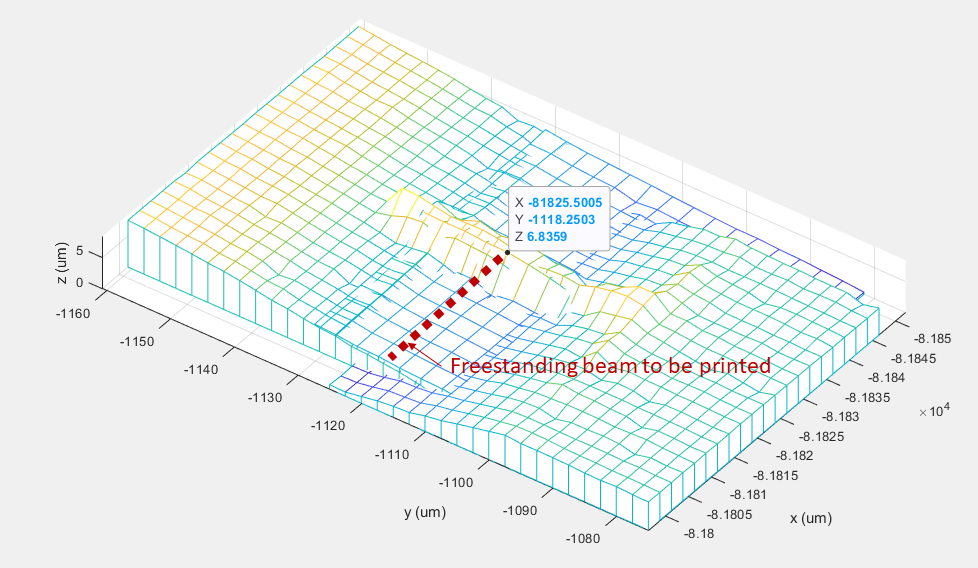
Another use of the mapping workflow is to image small, specific areas of a substrate and use the resulting topological image to align a structure more precisely than the pinpoint positioning feature, limited by the optical resolution from the top camera (few microns). With this approach, the imaging resolution is limited by the XY pitch of the measurement grid and the aperture diameter of the tip.
Prerequisites
The following steps must be validated to use the mapping workflow as a topological analysis tool:
- The whole system is accurately calibrated
- The laser is aligned and maximized
- No pressure is applied as approaching the substrate could lead to the deposition of material and the clogging of the tip
- The 3D printing calibration is completed
Scanning pre-existent structures
- From the top view, center the screen on top of the area to scan.
- Enter the Mapping workflow. Set a retract height larger than the maximum
height of the structures to be scanned to avoid any side collisions.
Optimize the number of points, approach speed and setpoint before clicking
OK. - The stages moves to the corresponding and scans around the target point as defined in the workflow. The stages go back to their original position at the end of the scan.
- Use the voxel cloud generator or the MATLAB workspace to plot the surface and read the absolute coordinates of the scanned area.
Absolute positioning
- Image the area where the structure needs to be printed
-
Use topographical analysis to determine the start position (e.g. with the voxel cloud generator)
-
Create a print file with the determined start position
- Print the new file without any changes
Note
Make sure to not change any parameters of the calibrated system. Otherwise, the positioning might be off and mapping has to be performed again.