3D Printing Calibration
This section describes how to accurately calibrate the system after preparing it. This is necessary for accurate printing in the 3D Printing workflow as the system might feature small inaccuracies such as due to a freshly mounted probe.
This workflow prints a simple structure and allows the user to align the preview of the structure with the actually printed structure. The difference in position is saved and applied to future print runs which results in accurately positioned print structures.
1. Prerequisites
- The printing chamber is prepared and connected to the potentiostat
- Potentiostat is running and an appropriate potential is applied (check whether the expected background current flows)
- The reservoir of the iontip is filled with the metal ion containing “ink” solution
- The iontip is gripped, the channel is filled with the ink and the laser is aligned
- The optical deflection signal has been maximized inside the printing chamber
- A printing file with a suitable calibration structure is prepared. A simple pillar suffices as a calibration structure.
2. Performing the calibration
Enter the 3D Printing Calibration workflow.
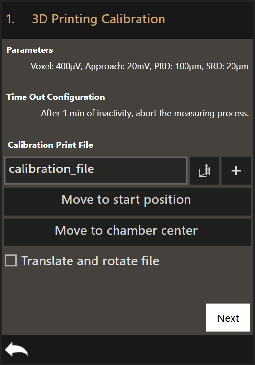
- Set the right printing parameters
- Select a calibration print file
- Start printing
- Measure the offset
You also have the option to measure the offset of an already printed structure. Simply select the print file of the printed structure.
- Select the already printed print file
- Measure the Offset
Optional
- Time Out Configuration
- If the printing process comes to a halt, the system waits this specified amount of time before aborting the print.
- Move to start position
- Moves the top view camera to the start position of the currently selected file.
- Move to chamber center
- Moves the top view to the center of the printing chamber. This usually corresponds to the center of the substrate.
- Translate and rotate file
- Apply a translation and a rotation to the print file. This allows you to place a print file at any position within the accessible area of the substrate.
3. The printing parameters
Clicking on Parameters will open the Print Configuration dialog where the
printing parameters can be set. The default values are loaded every time the
software is started.
This is the Print Configuration dialog:
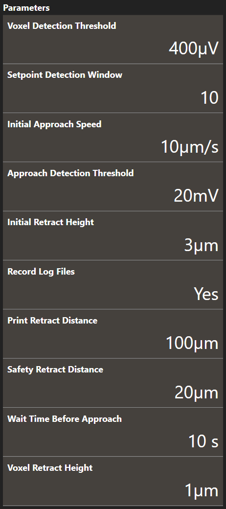
- Voxel Detection Threshold
- The cantilever deflection setpoint that defines voxel completion. The setpoint is relative. It is recommended to use 0.4 mV for printing pressures of up to 200 mbar. Above 200 mbar, 1 mV is recommended.
- Setpoint Detection Window
- The amount of sample points used for threshold detection of the cantilever deflection signal. The first sample of the window is subtracted from the last sample of the window. If the result exceeds the voxel detection threshold, a voxel completed event is triggered. It is recommended to use the LogViewer and analyze the deflection data to find a correct window size.
- Initial Approach Speed
- The approach speed of the cantilever at the start of the printing run. Maximum recommended speed is 20 µm/s.
- Approach Detection Threshold
- The cantilever deflection setpoint in Volts that has to be reached when the system first approaches the sample before printing. The tip will approach the sample at (X0, Y0). If the Approach Detection Threshold has been reached, the software defines the current z-position as Z0.
- Initial Retract Height
- After the tip has reached the substrate surface at (X0, Y0, Z0) it retracts the distance specified here and continues to the first voxel location at (X1, Y1) travelling at the defined height above the substrate surface.
- Record Log Files
- Set to
Yesto gather information while printing and store it in log files. The log files are described here. - Print Retract Distance
- To avoid collisions when moving from one print structure to the next one, this distance is added to the currently defined content height when moving to the start position of the next print structure.
- Safety Retract Distance
- The distance to retract after a print structure has been printed. This helps to mitigate collisions with already printed structures.
- Wait Time Before Approach
- The time to wait after 0 mbar has been applied but before the approach starts. This prevents false deflection detections as the tip might still oscillate during the approach if no wait time is used.
- Voxel Retract Height
- The distance to retract each time after a voxel has been printed. 1µm is generally recommended for standard 3D printing.
4. Add files
Clicking on + opens up a file selection dialog. You can add only a single
file.
To see a 3D visualization of the voxels in the print file, you can click on the
graph icon next to the + button.
5. Start printing
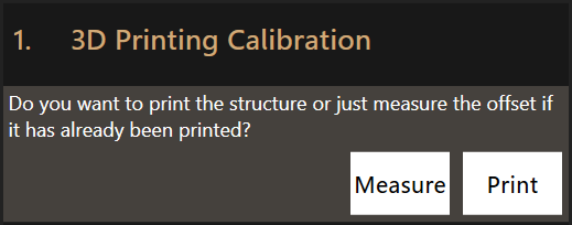
Clicking Next will give you the option to print the file or just use it as a
basis to measure the offset. Click Print to print the calibration structure
before measuring its offset or Measure to measure the offset of an already
printed structure.
6. Measure the offset
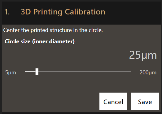
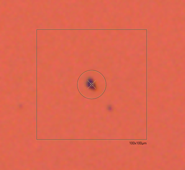
After successfully printing a calibration structure, the workflow allows you to measure the offset by dragging on the video feed to align the center of the video feed on the structure.
Click Save. The measured offset will be automatically applied to all future
print runs.
7. Log Files
The 3D Printing Calibration workflow outputs the same log files as the 3D Printing workflow.