Prepare Printing Chamber
This chapter describes how to prepare the CERES printing chamber before a printing session.
Printing chamber
The CERES printing chamber consists of the following parts:
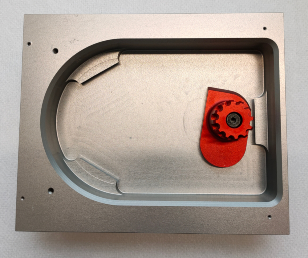
Base plate
Aluminum base plate with build-in locking and positioning mechanism
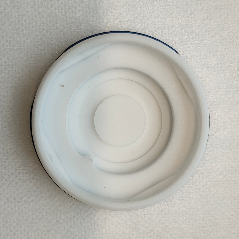
Cell Body
Teflon part provided with a rigid anodized aluminum ring at the bottom
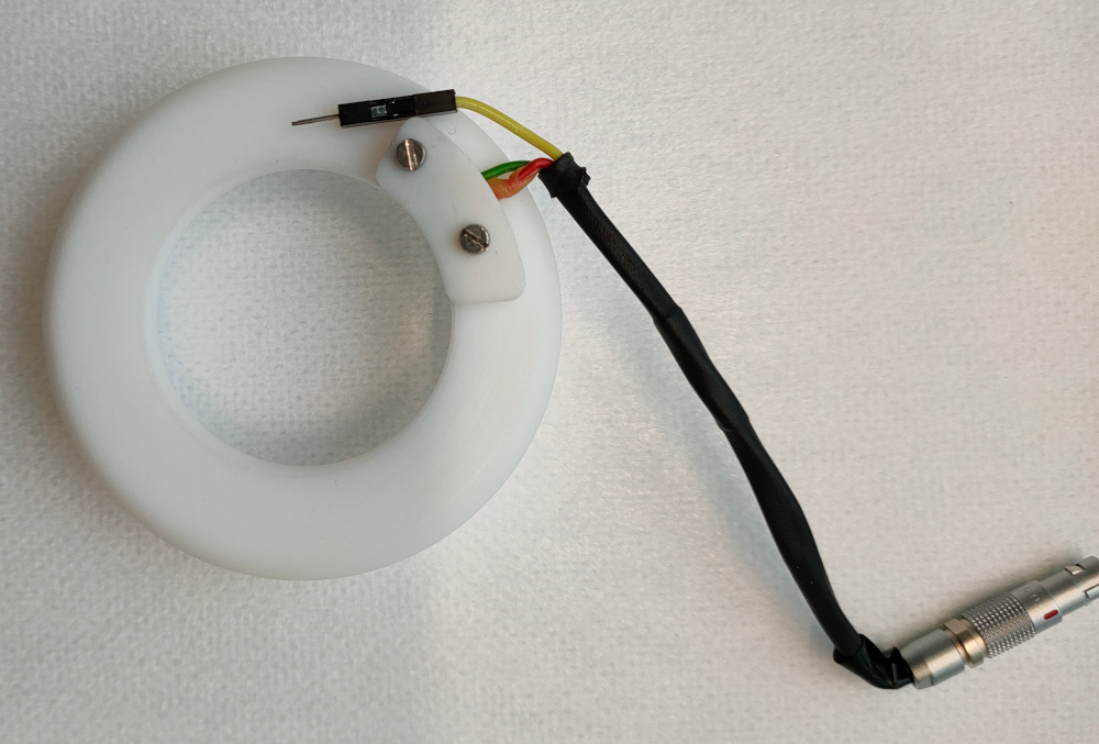
Clamping Ring
Teflon part fitted with gold terminals to the chamber, a jumper connector and, a lemo plug to the XY stage sled
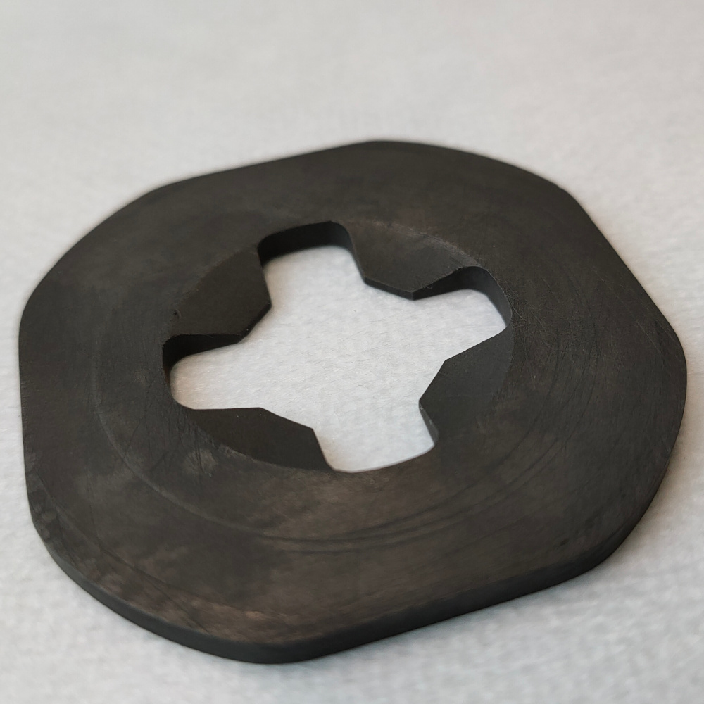
Counter Electrode
Graphite L shaped ring
Working Electrodes
The working electrode is composed by two graphite pieces: a connecting ring and base. The latter comes in 2 different dimension to accommodate different substrates dimension (15 mm x 15 mm or 25 mm x 25 mm)
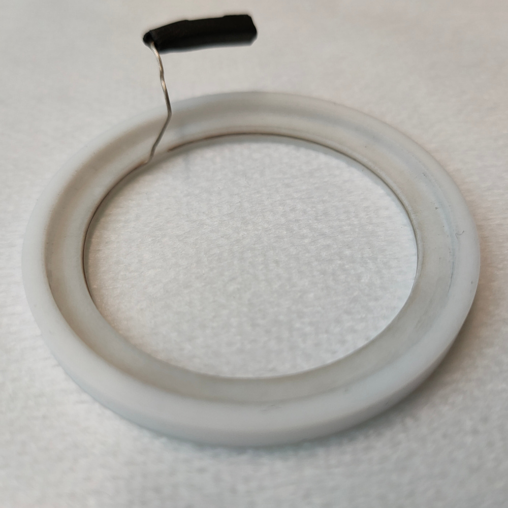
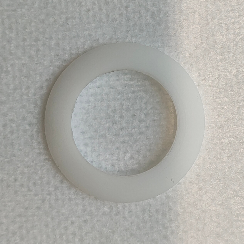
Reference electrode
Teflon ring fitted with a inlayed Ag/AgCl wire
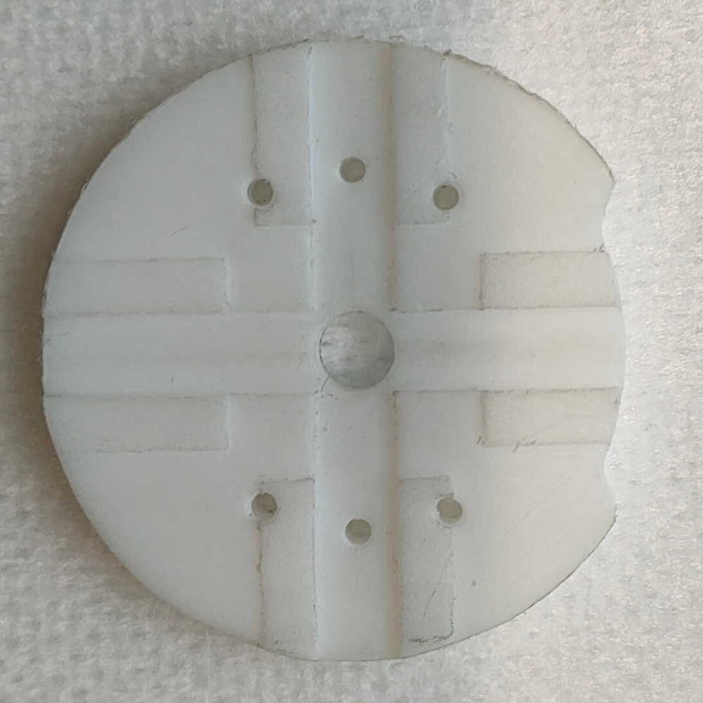
Substrate holders
Two teflon parts with differently sized cuts to fit different substrates dimension (15 mm x 15 mm or 25 mm x 25 mm)
Teflon spring
Telfon part shaped like a truncated cone
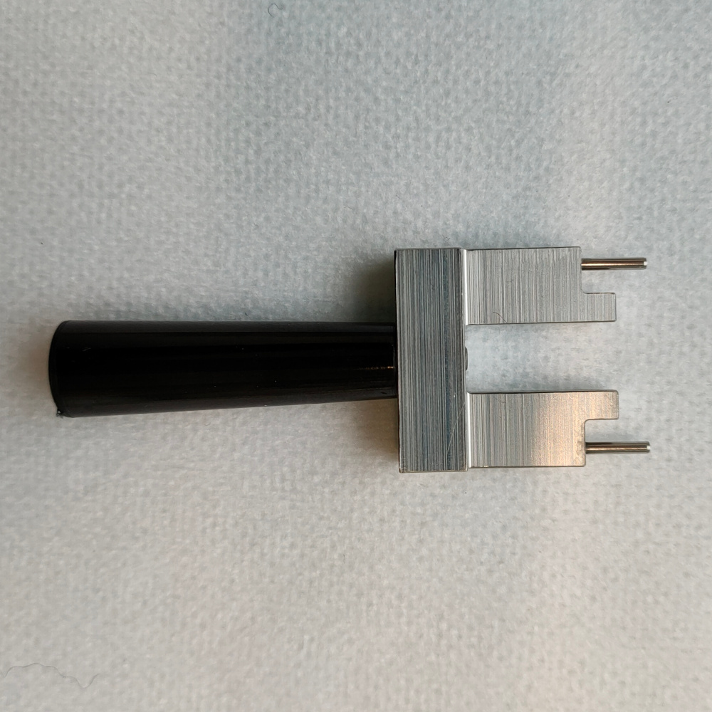
Sample exchange tool
Two custom sample exchange tools to be used with different substrates dimension (15 mm x 15 mm or 25 mm x 25 mm)
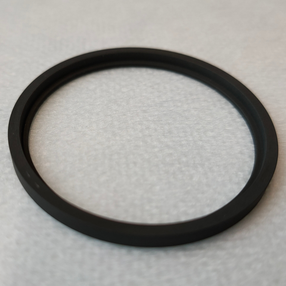
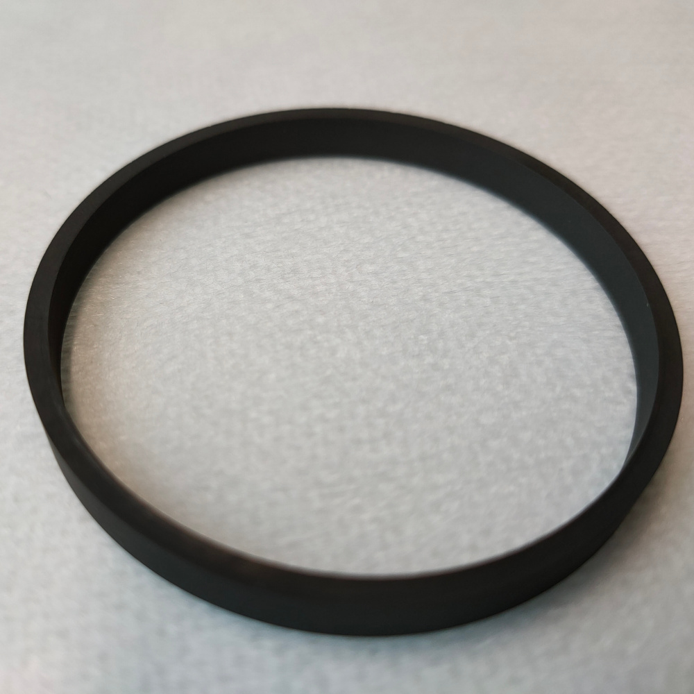
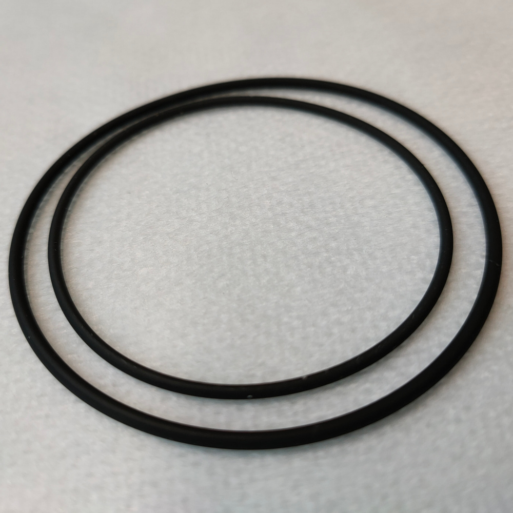
Sealing o-rings
A FKM 70 55.0x1.5 and a FKM 70 46.0x1.5 o-ring
Materials
The following materials are needed for the chamber preparation:
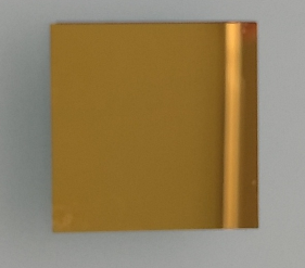
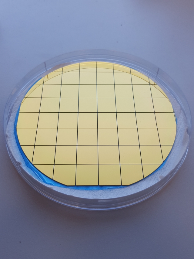
Working electrode
A printing substrate (15 mm x 15 mm or 25 mm x 25 mm). The image shows a substrate coated with a Ti adhesion layer and 125 nm Au on top.
Supporting electrolyte
The standard CERES supporting electrolytes can be used, or any other suitable solution.
Pasteur pipette / measuring cylinder
To measure and place/replace the supporting electrolyte into the chamber
Chemicals
To clean the working electrode (one WE cleaning example is described here).
Clean water
Deionized water could be sufficient, but Ultrapure / type I. (ASTM D1193) water (with resistivity = 18 MΩ·cm at 25 °C) is suggested
Chamber and substrate preparation
1. Assembling the chamber for printing
- Insert the teflon spring in the cell body with the taper facing up
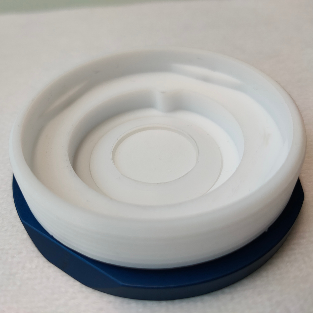
- Add the desired substrate holder making sure that it is free to rotate
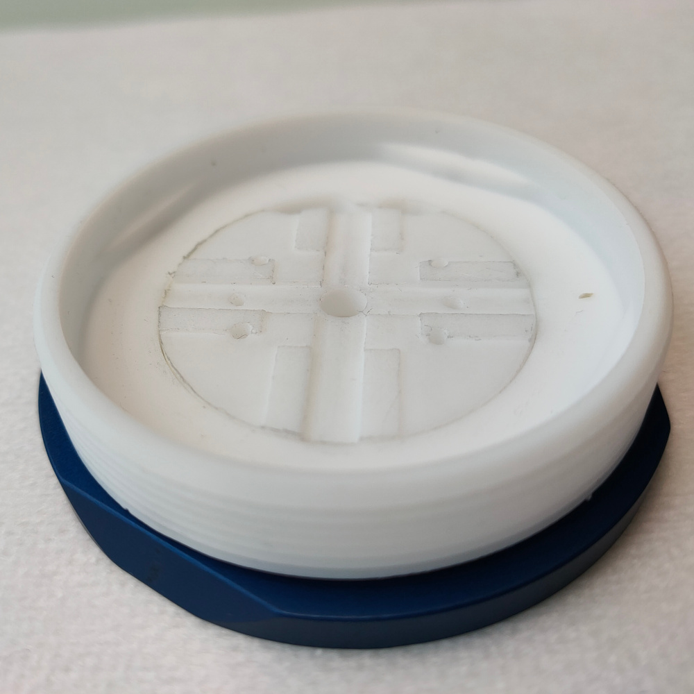
- Add the desired working electrode base with the flat surface facing down
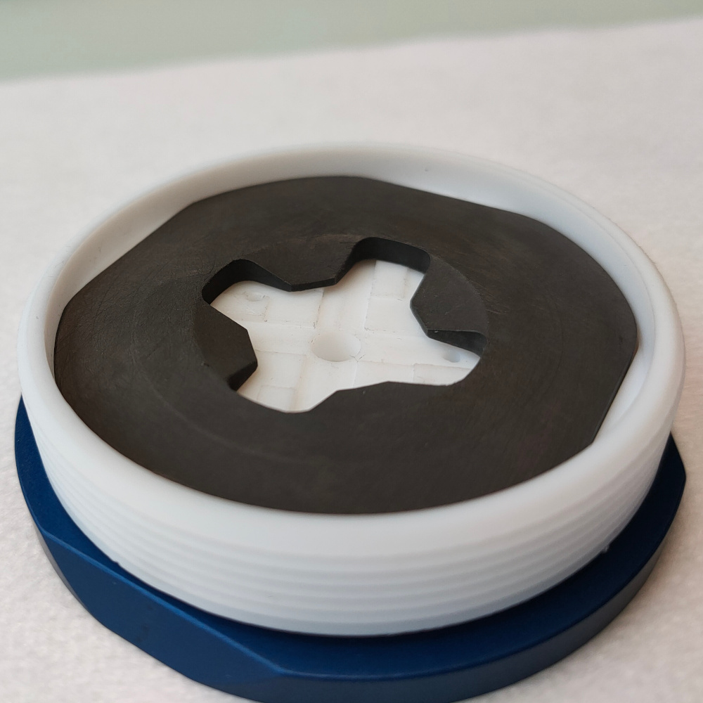
- Slide the working electrode connecting ring on the reference electrode making sure that the graphite of the connecting ring is slightly below the teflon of the reference and insert the assembly in the chamber
- Add the counter electrode
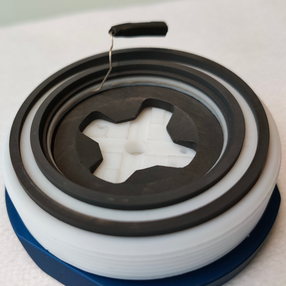
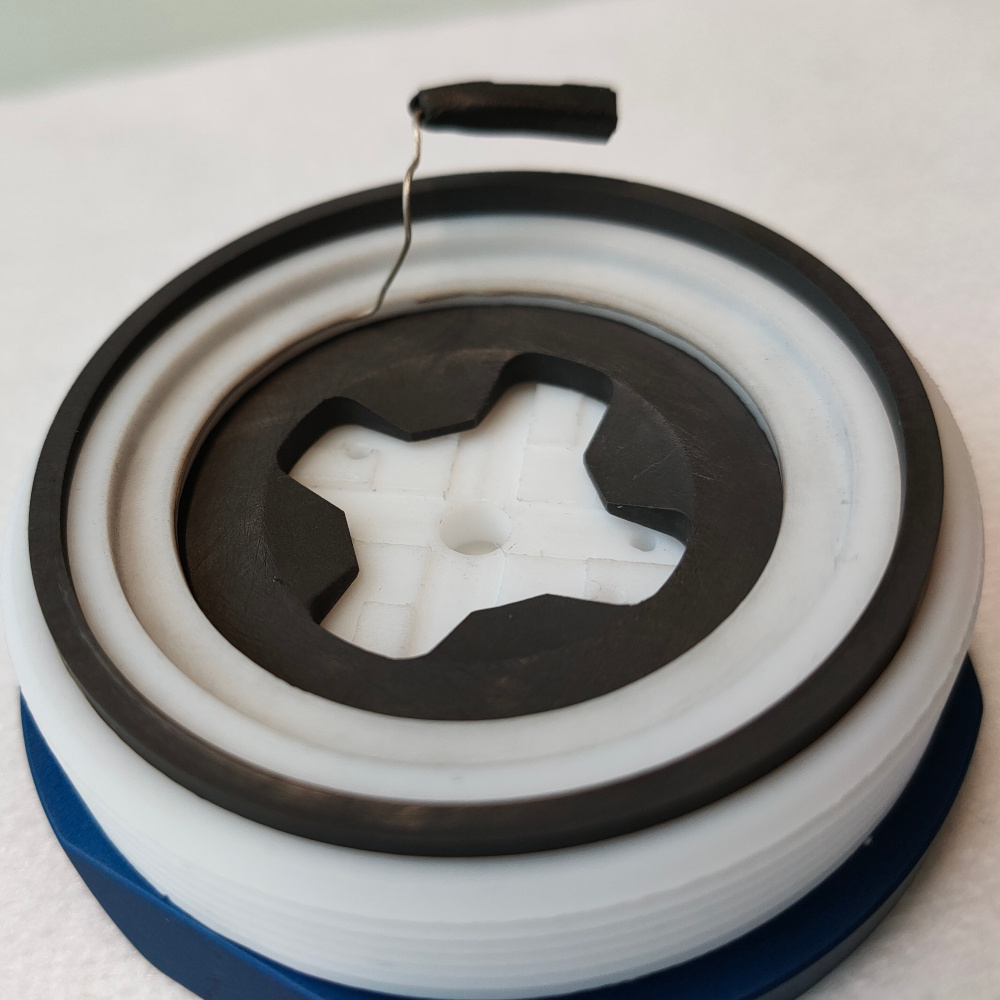
- Position the two o-rings on top of the chamber as shown making sure that the top surfaces of the graphite rings are not obstructed
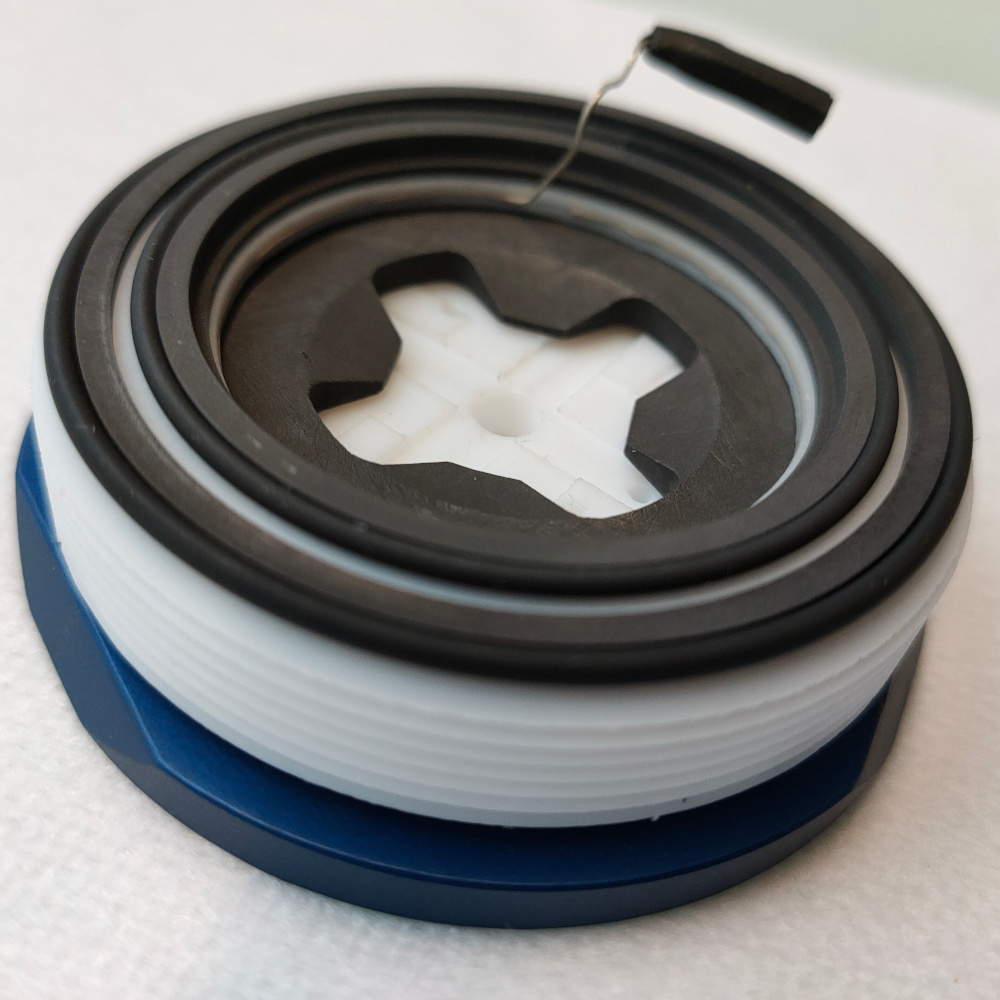
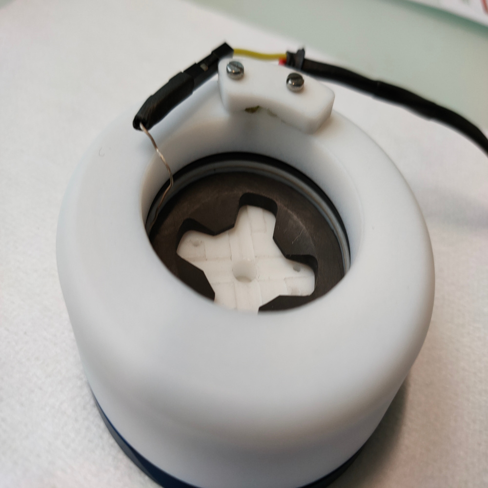
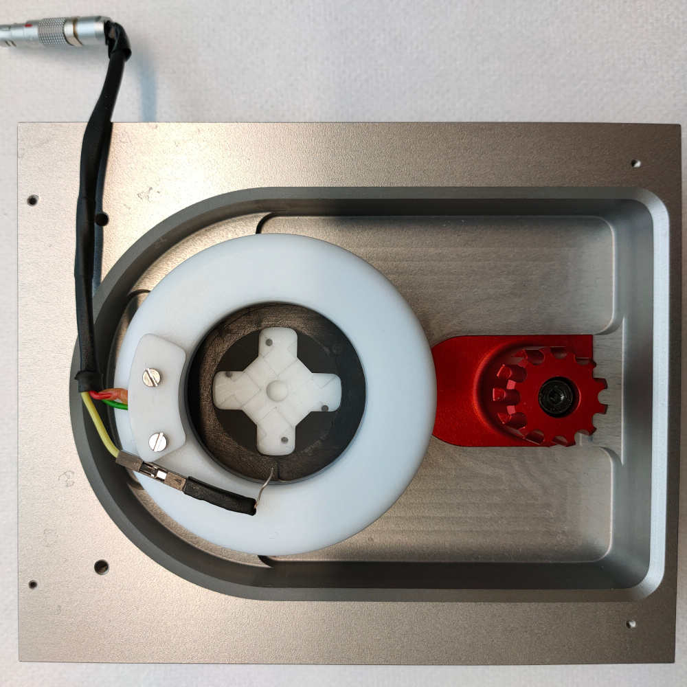
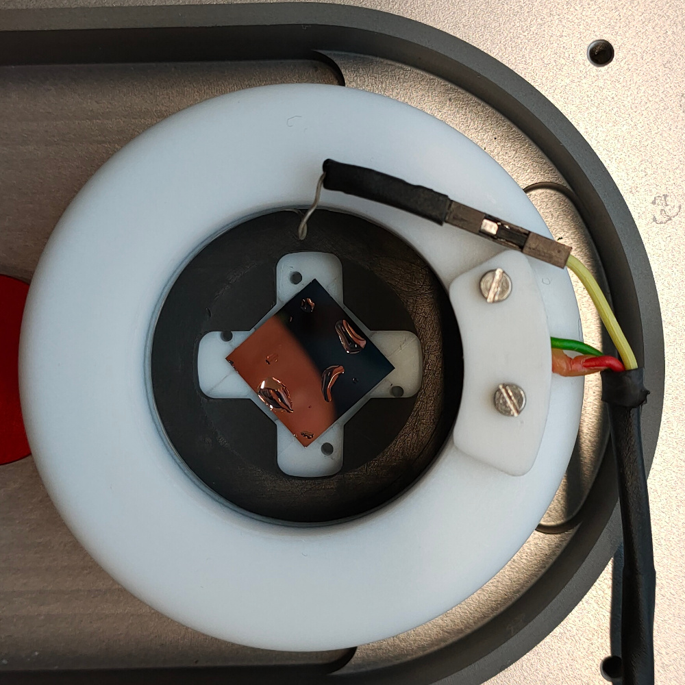
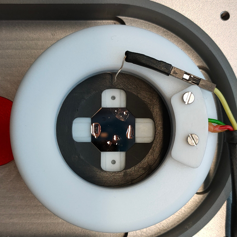
- Screw the clamping ring on top of the chamber making sure that the reference electrode connector is positioned on the right side of the cable tension relief block and flettened on the clamping ring as shown. Ensure that the silver wire is not in contact with any of the graphite pieces.
Note
The reference ring is free to rotate while screwing the clamping ring Make sure the cell is thightly screwed so that o-ring are being compressed
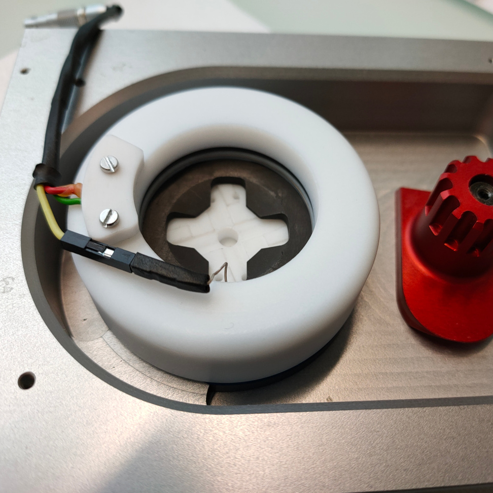
- Slide the assembled chamber in the base plate as shown (connector on the external side of the plate) and engage the locking mechanism
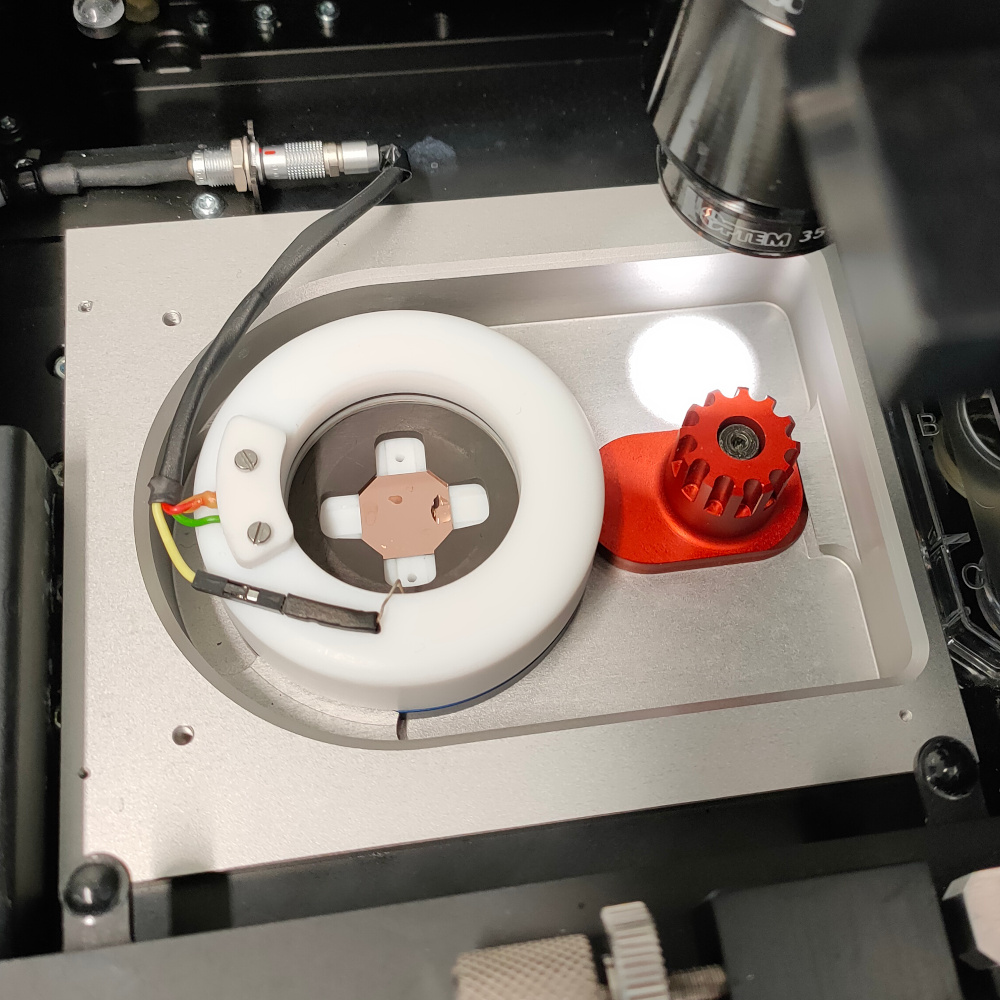
- Place the base plate with the chamber in the XY stage sled and connect the lemo plug
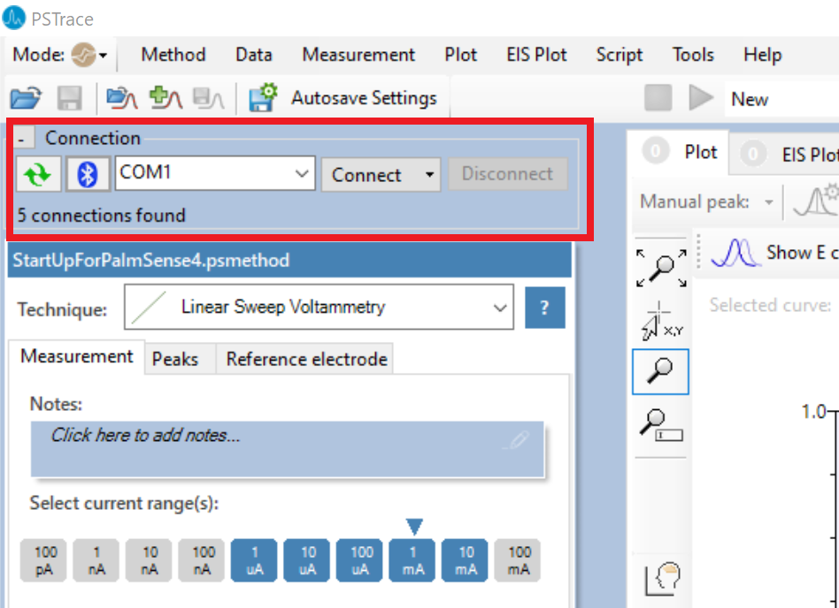
- Open the PSTrace software that control the potentiostat. Select
Emstat4in the dropdown list anc clickconnect.
- Go to the the
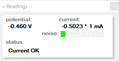
Manual controltab and make sure the control is set toE. Change the current range to10mA, enter the relevantpotentialvalue, clicksetthencell on.
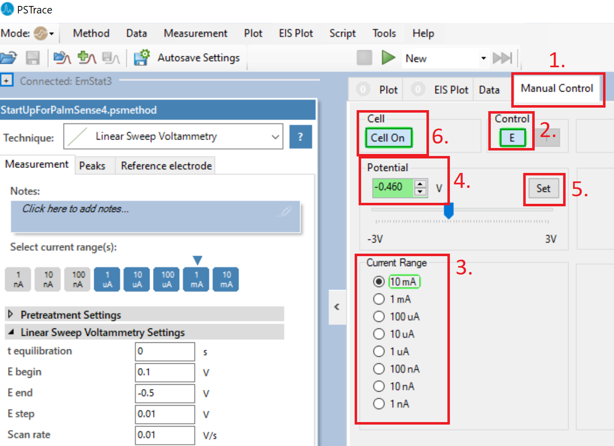
- A
readingwindow should appear confirming the potentiostat is controlled in the chamber. The cell button and potential field also become highlighted in green in the pstrace software (as on the image above).
-
Fill up the chamber with approx. 10-12 ml of the supporting electrolyte. The liquid level should be 1 to 2 mm higher than the counter electrode. Be aware of evaporation for prints of many hours.
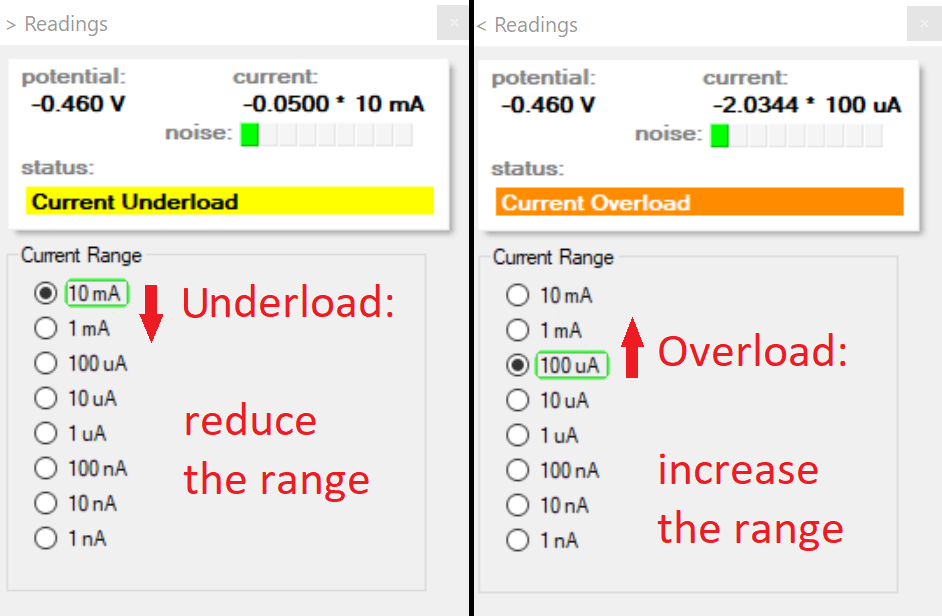
-
The current range can be changed to fit the current exchanged in the cell: An undercurrent means you can reduce the range used. An overcurrent means you need to increase the range used.
2. Substrate Preparation
This chapter is an example protocol for cleaning a gold substrate. Other substrate materials can be used and they may require their own substrate cleaning processes.
- Take one of the previously diced gold coated wafer pieces with a tweezer from the wafer holder
-
Rinse with acetone from a wash bottle (to remove the protective photoresist and to dissolve the majority of the organic contaminations from the surface)
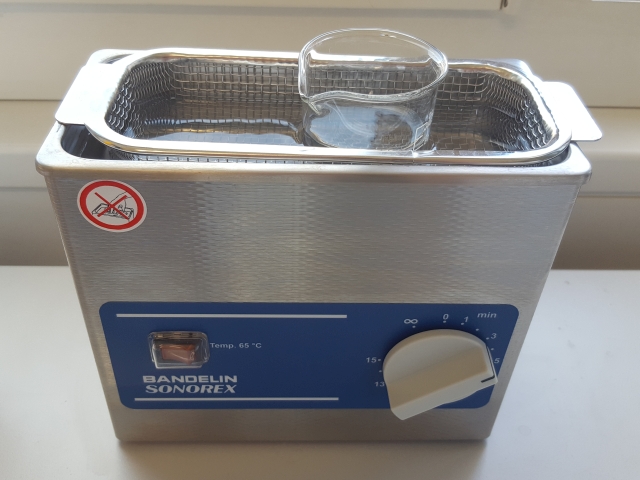
-
Place inside a beaker of acetone and sonicate it for at least one minute
- Rinse the substrate with isopropanol from a wash bottle
- Place inside a beaker of isopropanol and sonicate it for at least one minute
- Rinse the substrate with deionized water (ultrapure water is recommended)
- Place inside a beaker of deionized water and sonicate it for at least one minute
- Rinse with deionized water (ultrapure water is recommended)
3. Substrate Loading
Substrates can be inserted or swapped without the need to disassemble the chamber or, remove/disconnect it from the CERES system.
- To remove a substrate using the sample exchange tool press and rotate the substrate holder counterclockwise. Using a pair of tweezers remove the substrate from the chamber
- To insert a substrate place it in alignment with the holder (make sure the holder is in the release position: fully rotated counterclockwise) and press and rotate with the tool clockwise. The substrate corners should be directly below the graphite lobes of the working electrode base.
Note
This operation can be performed with the supporting electrolyte in the chamber and the deposition potential applied.
It is actually recommended to load the sample after the chamber is filled, the potential stable and the current in the usual order of magnitude for any given supporting electrolyte.
4. Chamber cleaning procedures
During a printing session, the supporting electrolyte should be replaced every 24 hours, however it’s possible to simply remove the used supporting electrolyte with a pipette and refill the cell with fresh electrolyte.
At the end of a printing session, the cell should be emptied, disconnected and removed from the CERES system.
If the successive printing session is planned with the same supporting electrolyte, it is sufficient to rinse the inside of the cell with deionized water without disassembling it.
In case a change in supporting electrolyte is planned, all part of the cell with the exception of the clamping ring, the reference electrode and the o-rings should be rinsed in water then isopropanol and finally left soaking in deionized water overnight. The clamping ring, the reference electrode and the o-rings should only be rinsed with deionized water.
Note
- Between two printing sessions, avoid exposing the reference electrode to substances that could affect the electrochemical characteristics of the materials. If possible rinse the reference electrode after use and store in a clean, dry, closed and dark environment. If necessary the Ag wire can be stripped clean and re-chlorinated.
- Do not heat or stress the parts. Teflon could deform.
- Do not use strong organic solvent on the clamping ring. Resin may dissolve, exposing the contact to the cell.
- Carbon flakes could form when the graphite parts are wiped. Sonication in successive fresh deionized water baths is recommended until the water stays clean.