3D Printing
1. Prerequisites
- The printing chamber is prepared and connected to the potentiostat
- Potentiostat is running and an appropriate potential is applied (check whether the expected background current flows)
- The reservoir of the iontip is filled with the metal ion containing “ink” solution
- The iontip is gripped, the channel is filled with the ink and the laser is aligned
- The optical deflection signal has been maximized inside the printing chamber
- A printing file is prepared
- There should be no pending Windows updates as they might interfere with the printing process
Additionally, the system can be calibrated using the 3D Printing Calibration. This allows for more accurate printing.
2. Printing in a nutshell
Navigate into the 3D printing workflow:
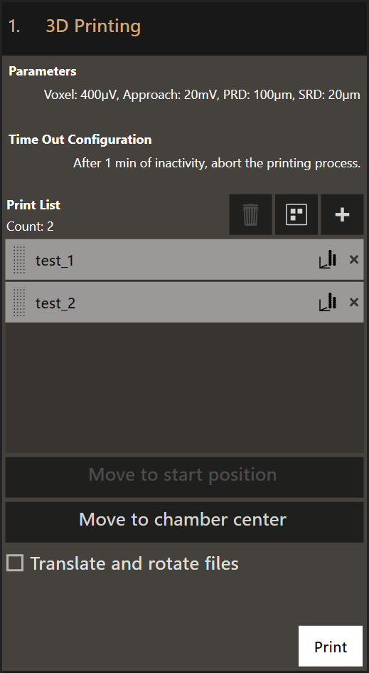
- Set the right printing parameters
- Add at least one print file to the list
- Start printing
Optional
- Time Out Configuration
- If the printing process comes to a halt, the system waits this specified amount of time before executing a time out action. You can choose one of the following actions:
- Abort the whole printing process
- Pause the printing process
- Cancel printing the current structure and continue with the next one
- Cancel printing the current structure and pause the printing process
- Move to start position
- Moves the top view camera to the start position of the currently selected file.
- Move to chamber center
- Moves the top view camera to the center of the printing chamber. This usually corresponds to the center of the substrate.
- Translate or rotate files
- Apply a transformation (translation and rotation) to each file that is printed. This allows you to place a print file at any position within the accessible area of the substrate.
3. The printing parameters
Clicking on Parameters will open the Print Configuration dialog where the
printing parameters can be set. The default values are loaded every time the
software is started.
This is the Print Configuration dialog:
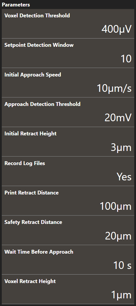
- Voxel Detection Threshold
- The cantilever deflection setpoint that defines voxel completion. The setpoint is relative. It is recommended to use 0.4 mV for printing pressures of up to 200 mbar. Above 200 mbar, 1 mV is recommended.
- Setpoint Detection Window
- The amount of sample points used for threshold detection of the cantilever deflection signal. The first sample of the window is subtracted from the last sample of the window. If the result exceeds the voxel detection threshold, a voxel completed event is triggered. It is recommended to use the LogViewer and analyze the deflection data to find a correct window size.
- Initial Approach Speed
- The approach speed of the cantilever at the start of the printing run. Maximum recommended speed is 20 µm/s.
- Approach Detection Threshold
- The cantilever deflection setpoint in Volts that has to be reached when the system first approaches the sample before printing. The tip will approach the sample at (X0, Y0). If the Approach Detection Threshold has been reached, the software defines the current z-position as Z0.
- Initial Retract Height
- After the tip has reached the substrate surface at (X0, Y0, Z0) it retracts the distance specified here and continues to the first voxel location at (X1, Y1) travelling at the defined height above the substrate surface.
- Record Log Files
- Set to
Yesto gather information while printing and store it in log files. The log files are described here. - Print Retract Distance
- To avoid collision when moving from one print structure to the next one, this distance is added to the currently defined content height when moving to the start position of the next print structure.
- Safety Retract Distance
- The distance to retract after a print structure has been printed. This helps to mitigate collisions with already printed structures.
- Wait Time Before Approach
- The time to wait after 0 mbar have been applied but before the approach starts. This prevents false deflection detections as the tip might still oscillate during the approach if no wait time is used.
- Voxel Retract Height
- The distance to retract each time after a voxel has been printed. 1µm is generally recommended for standard 3D printing.
4. Add files
Clicking on + opens up a file selection dialog. You can add any number of
files.
Click and drag the dotted area left of the file name tag to reorder manually. Clicking on the graph icon on the right of the file name tag gives a 3D visualization of the voxels in the print file.
5. Start printing
Clicking Print will immediately start the printing run. The printing can be
started at any tip position and continues until the last print file in
the task list has been printed.
6. Progress monitoring
The progress monitor contains several items:
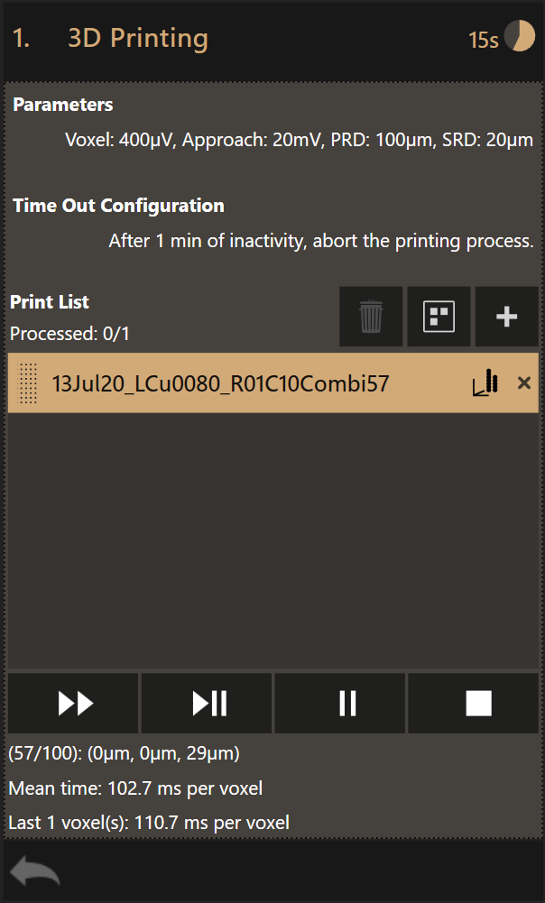
By clicking +, more print files can be added to the task list. Clicking on the
X mark on the right of a file name tag removes the file from the task list.
The order of the files can be swapped by clicking on the dotted area of a print file entry and dragging it to the desired position.
There are four controls displayed at the bottom of the dialog that allow (from left to right):
- Skip a file and continue with the next
- Pause and abort current
- Pause after current
- Abort printing
While printing is paused, the parameters and time out configuration can be changed.
A print file that has been printed will be grayed out but still visible in the list.
As soon as the printing stops the files that have printed will be removed from the task list. The files that have not been printed remain in the list.
At the top right the estimated print time remaining is shown.
At the bottom, a count down timer shows the active voxel as a fraction of the total amount of voxels in the current print file. Voxel 57 out of a total 100 voxels is being printed in this example. The location (x, y, z) of the active voxel and the mean time, calculated over the already printed voxels, are displayed.
The last voxel duration is shown as well. In case the voxel print duration was very short, the aggregated printing time of multiple voxels is displayed.
The name of the active print file is highlighted. Clicking the graph icon on the right displays a 3D rendering of the design.
Note
The Z coordinate of the active voxel gives valuable information about the tip - sample separation. If the system does not print, it could be that the Z coordinate specified in the .csv file is incorrect. It should be very close (few 100 nm to max. a few µm from the surface).
7. Log Files
The workflow produces three different log files per print file. All files are
saved to %USERPROFILE%/Documents/Exaddon/Print Data.
Each file features a header row containing the version and type of the file as well as another row representing column headers.
Deflection Log
The deflection log contains records with the current deflection and Z level of the probe. The deflection and positioning signals are sampled with a rate of 1384 Hz.
The deflection log has got the following naming scheme:
{YYYY-MM-DD-HH-MM-SS}_{print file name}_DL.txt
Example:
2019-12-03-11-27-57_02Dec19_test_R12C10Combi57_DL.txt
The file is structured as follows:
V1 DeflectionLog Exaddon
Deflection [V],Z level [mm]
{deflection in Volts},{Z level in mm}
{deflection in Volts},{Z level in mm}
{deflection in Volts},{Z level in mm}
...
Example:
V1 DeflectionLog Exaddon
Deflection [V],Z level [mm]
0.295096,-37.106999
0.295058,-37.106999
0.295095,-37.106999
0.295016,-37.106999
0.295038,-37.106999
0.295066,-37.106999
0.295015,-37.107000
0.295035,-37.107000
...
Voxel Log
The voxel log contains a record for each detected voxel. Each record shows the maximum deflection reached while printing a single voxel, the time it took to print the voxel and how the voxel was detected. Voxel log files follow this naming scheme:
{YYYY-MM-DD-HH-MM-SS}_{print file name}_VL.txt
Example:
2019-12-03-11-27-57_02Dec19_test_R12C10Combi57_VL.txt
The file is structured as follows:
V1 VoxelLog Exaddon
Deflection [V],Duration [ms],Detection Type
{max voxel deflection in Volts},{voxel duration in ms},{detection type}
{max voxel deflection in Volts},{voxel duration in ms},{detection type}
{max voxel deflection in Volts},{voxel duration in ms},{detection type}
...
The following detection types exist:
NormalCollisionPointAlreadyThere
Example:
V1 VoxelLog Exaddon
Deflection [V],Duration [ms],Detection Type
0.296185,393.064,Normal
0.296270,44.075,Collision
0.296303,53.468,PointAlreadyThere
0.296290,29.624,Collision
0.296298,28.902,Collision
0.296265,88.150,Normal
0.296205,43.353,Normal
0.296155,88.150,Normal
...
Properties Log
The properties log contains a list of parameters that were used to print a single structure. It uses the following naming scheme:
{YYYY-MM-DD-HH-MM-SS}_{print file name}_PL.txt
Example:
2019-12-03-11-27-57_02Dec19_test_R12C10Combi57_PL.txt
The file is structured as follows:
V2 PropertiesLog Exaddon
Parameter,Value
{parameter},{value}
{parameter},{value}
{parameter},{value}
...
Example:
V2 PropertiesLog Exaddon
Parameter,Value
TipType,Exaddon iontip 300
TipSerial,12341
ApproachDetectionThreshold,0.02
InitialRetractDistance,3.0000
InitialApproachSpeed,10.0000
SetpointDetectionWindowSize,10
SafetyRetractDistance,20.0000
PrintRetractDistance,100.0000
VoxelRetractHeight,42.0000
TranslationX,723.4383
TranslationY,-345.7024
RotationAngle,0
RotationCenterX,-81276.5617
RotationCenterY,527.2976
OffsetX,114.8761
OffsetY,-56.2925
WaitTimeBeforeApproach,10.0000
InitialStartHeight,-36590.1696
VoxelDetectionThreshold,0.0004
ApproachTickIndex,100557
VoxelsPrinted,27879
VoxelsTotal,329215
DevFlag,0
8. Tip cleaning
It can happen that the tip clogs during the printing process. The user can wash and recover the tip with the built-in washing tool. A well plate with washing liquids should be already loaded into the right port of the printer.
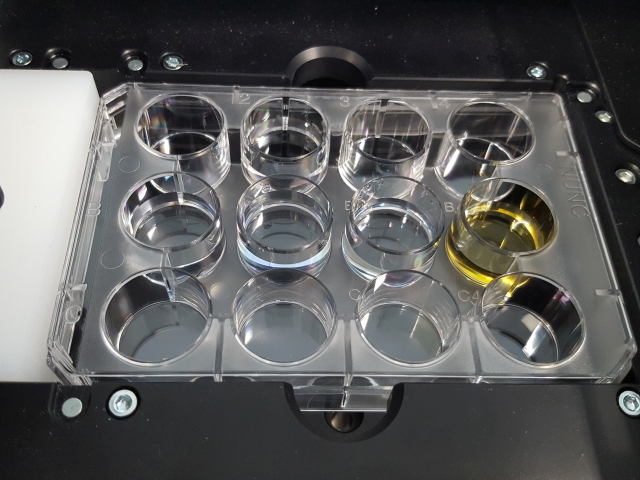
12-hole wellplate placed into the right port of the printer for tip washing
The following process is an example for washing a tip after printing Copper:
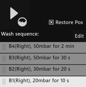
The above-mentioned screenshot shows an example of the following steps:
- Etching the cantilever inside a “Copper etching solution” at 50 mbar overpressure for 2 minutes in the B4 well.
- Rinsing the cantilever in B3-B2-B1 wells at different overpressures in demineralized water.
- After the washing process, the tip will move back to its original position,
if the
Restore Poscheckbox is checked.
Make sure that the potentiostat always applies an appropriate potential to the electrochemical cell to prevent dissolving of already printed structures. Even short interruption may lead to (partial) dissolution of structures that were already printed.