Design Scripts
This chapter describes the in-built design scripts provided with the VCG. Each of them allows to build a specific structure with voxels ready to be exported as a .csv file and printed. They are configurable via a list of parameters. For any script selected in the list:
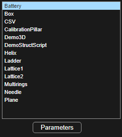
The Parameters button opens a table and a preview figure to modify the default values of the highlighted script.
After the parameters have been modified, Preview updates the plot for the new values and OK saves them and exits back to the main VCG window. Parameters are then saved until another script is selected in the script tab of the VCG.
Set as default changes the default values of this script for the current ones. Further selection of this script in the tab will load the new values to generate the default structure.
At the end of the page, a script template is described to ease the design of additional scripted structures.
Box
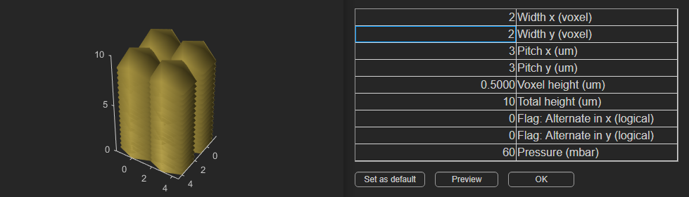
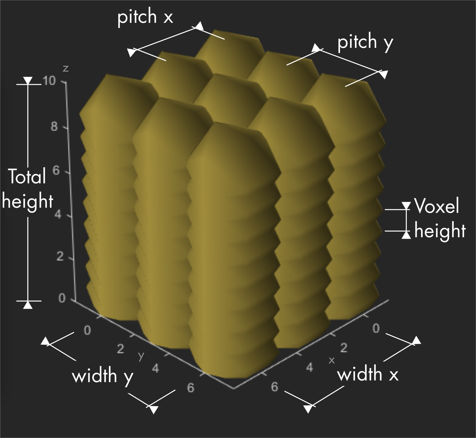
The Box script is used to generate simple cuboids.
| Parameters | Info |
|---|---|
| Width x | Width of the box in number of voxels along x direction. |
| Width y | Width of the box in number of voxels along y direction. |
| Pitch x | Spacing in µm between two voxels along x direction. |
| Pitch y | Spacing in µm between two voxels along y direction. |
| Voxel height | Spacing in µm between two horizontal layers of voxels. |
| Total height | Height of the cuboid in µm. |
| Flag: alternate in x | If set to 1 (yes), each even layer is shifted by 1/2 a pitch x along x. |
| Flag, alternate in y | If set to 1 (yes), each even layer is shifted by 1/2 a pitch y along y. |
| Pressure | Mbar applied for each voxel. |
Note
If width x = width y = 1, the box script gives a pillar. If Total height = Voxel height, the box script gives a plane of 1 layer.
Calibration Pillar
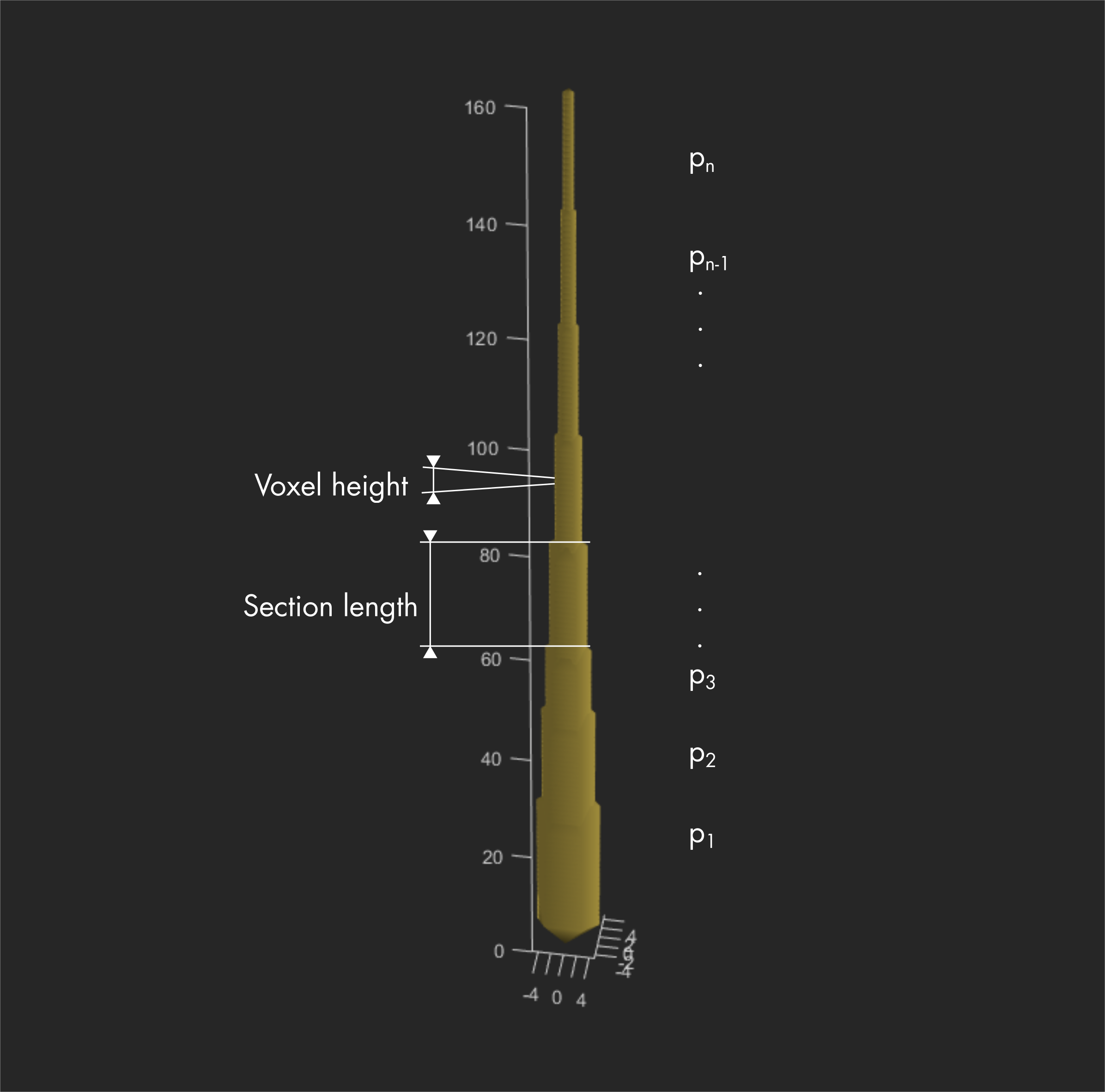
This pillar with sections printed at different pressures is used to calibrate the tip and provides an accurate prediction of the printed voxel diameter. The pressure list can be adapted to get enough points for the fit in the calibration workflow.
| Parameters | Info |
|---|---|
| Voxel height | Spacing in µm between two subsequent voxels |
| Section height | Number of voxels to print for each pressure in the list |
| Pressure list | List of pressure [p1,...,pn] in mbar, one section is created per value. |
Note
Accepted separators for the pressure list are commas and spaces.
CSV
This script loads an outsourced .csv file into the VCG rather than building it with scripts. The loaded .csv file must be in the right file format.
| Parameters | Info |
|---|---|
| Use CSV pressure flag | Default value (0) means the pressure parameter below will be used instead of the file’s pressure value(s) for all voxels. If set to 1, the pressure list is kept as loaded from the .csv file. |
| Pressure | Pressure in mbar replacing the loaded .csv pressure(s) when the flag above is set to 1. Multiple pressure values are lost. |
Note
The .csv file is kept in memory until another script is loaded. To load a new .csv file, use the load new csv button in the parameter editor or change the selected script in the VCG list and select CSV again.
Helix
The Helix script is used to create stranded spirals, helixes, coils or arcs of circles, cylinders cones or discs.
| Parameters | Info |
|---|---|
| Number of turns | Turns printed between the stat and finish point. |
| Initial height | Height in µm of the starting point. |
| Vertical separation | Height Δz in µm between two voxels separated by one turn. |
| Initial radius | Distance r in µm between the starting point to the axis of the coil. |
| Radial separation | Radius increment Δr in µm between two points separated by one turn. |
| Phase | Starting angle φ of the helix structure in respect to the x axis. |
| Voxel distance | Spacing in µm between two subsequent voxels. |
| Radial smoothing | Yes/no (1/0) option to smooth out the curvature when using non-null radial and vertical separation. |
| Starting pillar flag | If yes (1), a pillar is added below the starting voxel. |
| Final pillar flag | If yes (1), a pillar is added below the last voxel. |
| Support pillars flag | If yes (1), a pillar is added regularly to support the beam, defined by the support spacing parameter. |
| Support spacing | Spacing in µm between pillars if support pillars are used. |
| Pillar Z gap | Spacing between the pillar last voxel and the coil strand. |
| Pressure | mbar applied for each voxel. |
Note
If both vertical and radial separation are set to 0, the structure becomes a circle in the horizontal plane. A number of turns in [0,1] should then be used to avoid redundancy and collisions.
Coils use a radial separation of 0. Planar spirals use a vertical separation of 0.
If the vertical and radial separation are small enough, voxels can merge and create revolution surfaces like cones and cylinders. Resulting structures have the advantage to be seamless contrary to layer-by-layer approach, where a seam is usually observed between the first and last voxel of each layer.
Ladder
A ladder structure is composed of two vertical pillars linked by horizontal beams at a regular spacing.
| Parameters | Info |
|---|---|
| Voxel distance | Spacing in µm between two subsequent voxels. |
| Intersection distance | Spacing in µm between the last voxel of the horizontal beam and the last voxel of the pillar below. |
| Number of steps | Number of horizontal beams. |
| Step height | Distance in µm between two horizontal beams. |
| Step width | Width in µm of the ladder. |
| Pressure | mbar applied for each voxel. |
Multiring
This structure features two concentric rings rotated by 90° around the vertical axis.
| Parameters | Info |
|---|---|
| Outer ring radius | Radius in µm. |
| Inner ring radius | Radius in µm. |
| Bottom pillar height | Length in µm of the pillar below the largest ring. |
| Top pillar height | Length in µm of the pillar above the largest ring. |
| Voxel pitch | Spacing in µm between two subsequent voxels. |
| Pressure | mbar applied for each voxel. |
Needle
The needle script creates a hollow cylinder, beveled to obtain a sharp, thin tip.
| Parameters | Info |
|---|---|
| Needle radius | Radius in µm of the base cylinder. |
| Voxel pitch | Spacing in µm between two subsequent voxels in the same layer. |
| Voxel height | Spacing in µm between horizontal layers. |
| Height of the needle | Total height in µm of the needle. |
| Alternate flag | If set to 1 (yes), each odd layer is rotated to offset each voxel by 1/2 voxel pitch between each layer. |
| Bevel angle to vertical | Angle in degree, in the range ]0,90]. |
| Pressure | mbar applied for each voxel. |
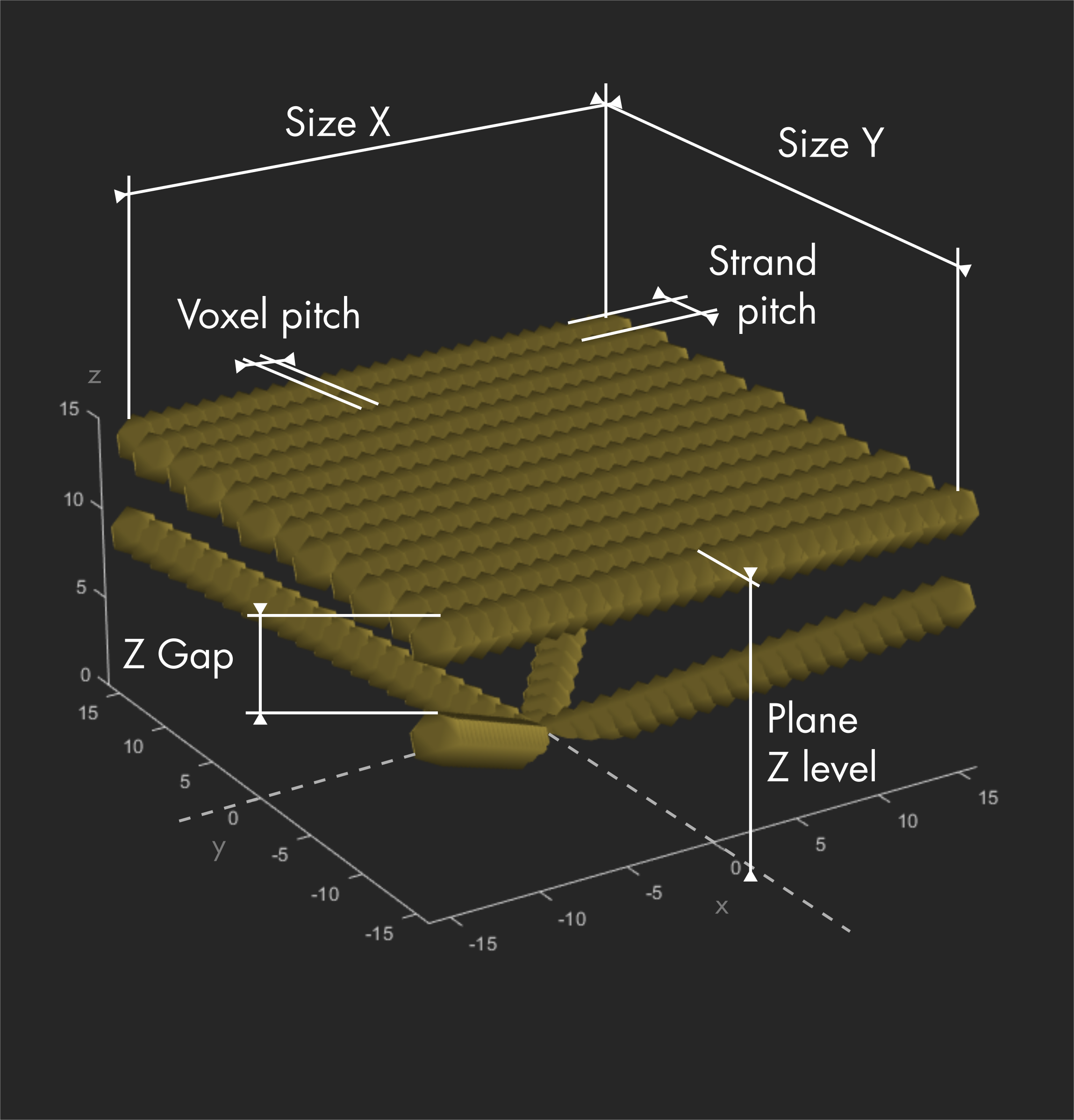
Plane
The plane script creates a flat, monolayered structure supported by beams in each corners of the plane and merging in a single base.
| Parameters | Info |
|---|---|
| Size X | Length in µm of the plane along the X direction. |
| Size Y | Length in µm of the plane along the Y direction. |
| Plane Z level | Height in µm of the plane. |
| Z Gap | Spacing in µm between the plane and the last voxels of the beams. |
| Voxel pitch | Spacing in µm between two subsequent voxels (spacing in the X direction). |
| Strand pitch | Spacing in µm between two strands (spacing in the Y direction). |
| Beams Flag | If set to 0 (no), no beams are added to the structure. |
| Pressure | mbar applied for each voxel. |
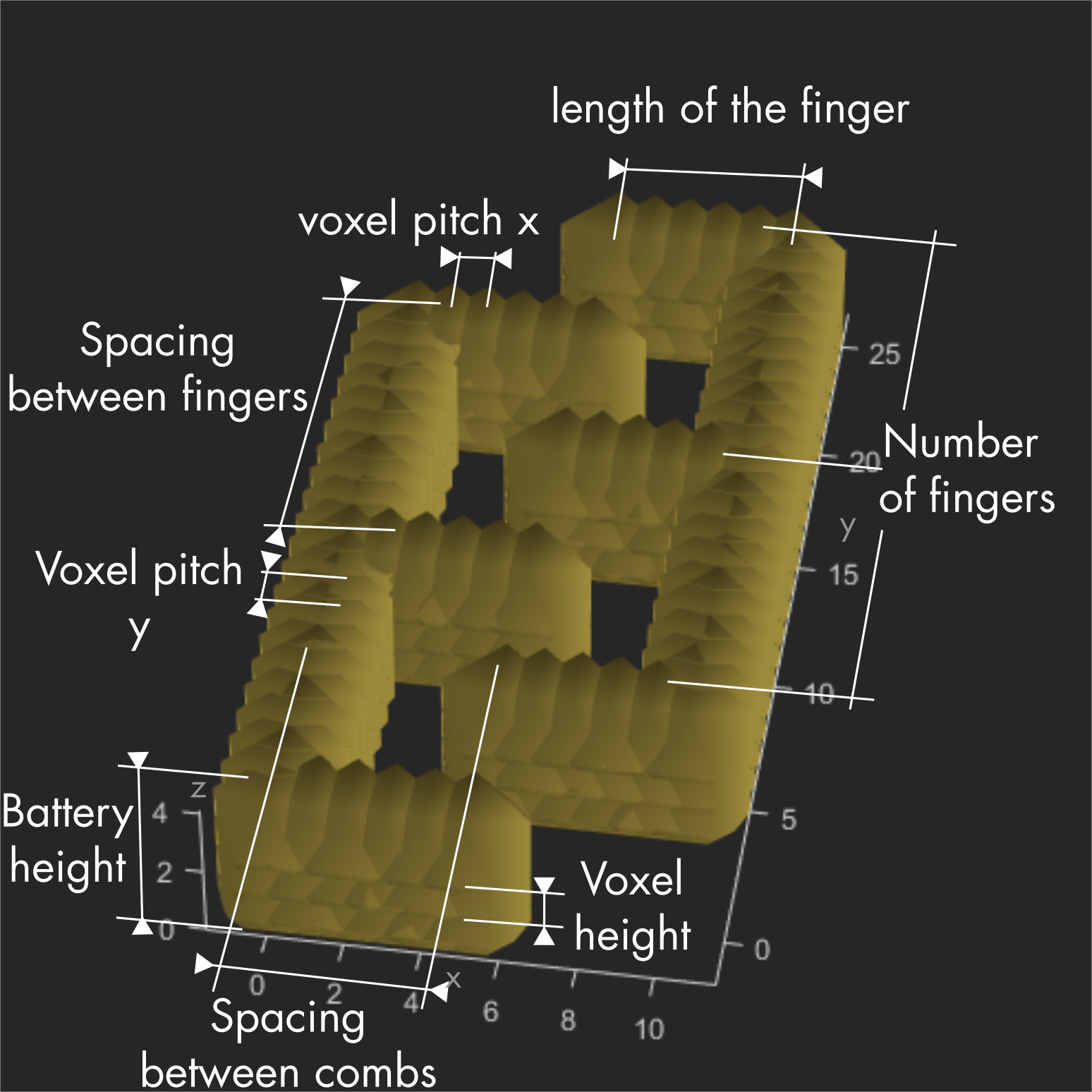
Battery
The Battery script creates two inter-digitated combs.
| Parameters | Info |
|---|---|
| Number of fingers | For each comb. |
| Spacing between fingers | Spacing in µm between two fingers of the same comb. |
| Length of the fingers | In µm. |
| Voxel pitch along X | Spacing in µm between voxels in the fingers. |
| Voxel pitch along Y | Spacing in µm between voxels in the wall. |
| Y spacing between combs | Distance in µm between the wall of one comb and the finger of the other comb. |
| Battery height | Total height in µm. |
| Voxel height | Spacing in µm between two voxel layers. |
| Alternating voxels flag | If set to 1 (yes), each even layer is shifted by 1/2 a pitch along the printing direction. |
| Pressure | mbar applied for each voxel. |
Demo structure script
Scripting a new structure design can be done in MATLAB. A template called DemoStructScript.m is provided in the /script subfolder of the the VCG main directory.
A script has 2 main components: the main function, providing the interface needed to use it within the VCG and functions for the voxel generation.
Preparing the template
The DemoStructScript.m file must first be copied to the /script directory and renamed (no spaces allowed).
The name given to the script will be the displayed name in the VCG scripts list.
MATLAB requires the first function (main function) to have the same name as the file. Remember that MATLAB is case sensitive.
For example, if the copied script template file was renamed AbC.m
change the first line:
function PD = DemoStructScript(parameters, CreateDefaultFlag, app)
into :
function PD = AbC(parameters, CreateDefaultFlag, app)
Locate the variable cells:
Variable    = {'var1';'var2';'pr'};
Description = {'Variable 1';'Variable 2';'Pressure'};
Value       = {'1 0';0;60};
Unit        = {'1';'um';'mbar'};
The Variable string cells contain the names of the variables used in the script generation function(s). Use '' to create strings.
The Description string cells contain a description for each variable and are displayed in the parameters table of the VCG. Units of the variables have their dedicated cells, omit them here.
The Value cells contain the initial values of each variable defined in the Variable cells. They are used to create the default parameter file in the /Standard_Structure_Folder subfolder.
This parameter file contains the default values loaded each time the script is selected in the VCG. It is overwritten each time the Set as default button is pushed.
The Unit string cells contain information on the unit of each variable. They are displayed between parenthesis in the parameters table of the VCG.
Enter the input variables used to generate the scripted structure. Change or add Variables and their corresponding Descriptions, Values and Units depending on what is needed to build a new scripted structure.
Note
The script support multiple values for each variable, used for example in the calibration pillar with the pressure list.
For any variable, instead of entering a single value value{i}=x, a string can be used instead with space or comma separators between each value for this single variable.
Value{i}='x1 x2,x3'.
In this example, the variable will be interpreted as an array of 3 values:
obj.variable{i} = [x1, x2, x3];
Since strings are interpreted as list of numbers, only numbers are supported as Values.
Generating the voxels
The function called that should contain the voxels generation is:
PD=MakeStruct(obj);
When the function is called, variables defined above are stored in the obj structure. To access them in sub-functions, the obj structure must be passed as an argument.
To access the value of a variable, use obj.VariableName. If the variable is an array, you can access its value using obj.VariableName(i), where i represents the index.
The output is a PD structure containing 4 arrays of dimension 1*n, for the X, Y, Z coordinates and the pressure value of each n voxels forming the structure:
PD.x = [vx1;...;vxn]; % use semicolon separator to get the array in n*1 dimension
PD.y = [vy1;...;vyn];
PD.z = [vz1;...;vzn];
PD.pr= [pr1;...;prn];
Use sub-functions to fill the PD structure with desired values.
The voxels should be generated in the order of printing to spare an additional routing step.
As a last step, test the script and verify the routing of its output. The routing can be simulated using the Show function of the VCG.