CERES Printer Manual
The goal of this manual is to give you the necessary information to operate the CERES additive micro-manufacturing (µAM) system. In this quick start guide, we give you a rough overview of the necessary steps to start printing your structures and where to find additional information.
Before starting a new experiment, make sure that the required hardware is powered on and connected.
Check if these components are turned on and connected to the system:
- CERES controller
- Microfluidics Control System
- Optical cameras (top and bottom view)
- Barcode reader
Additionally, refer to the SOP pages to prepare the following components:
Start-up
Start the CAPA operator software by double-clicking on its icon
![]() either on the desktop or in the
start menu under
either on the desktop or in the
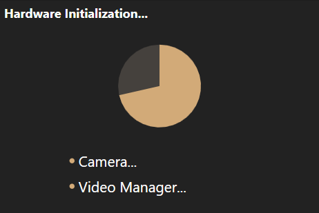
start menu under Exaddon. Wait while the application initializes and
configures connected hardware.
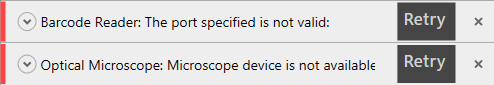
Note
Error messages will be displayed at the bottom of the screen if errors occurred during the initialization process. Pressing the expansion button on the left side shows detailed error information.
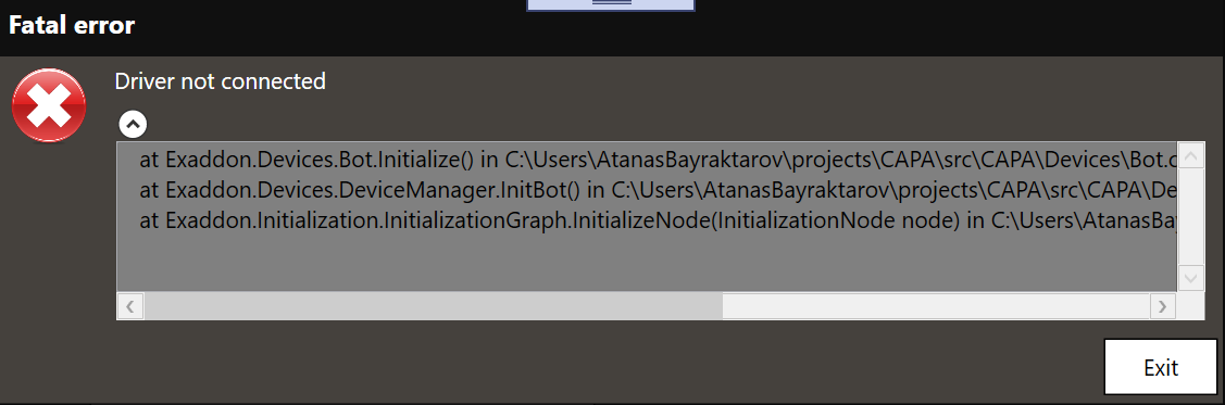
If a fatal error occurs during the initialization process, this dialog will be displayed. After clicking on the Exit buton, the application will immediately shutdown.
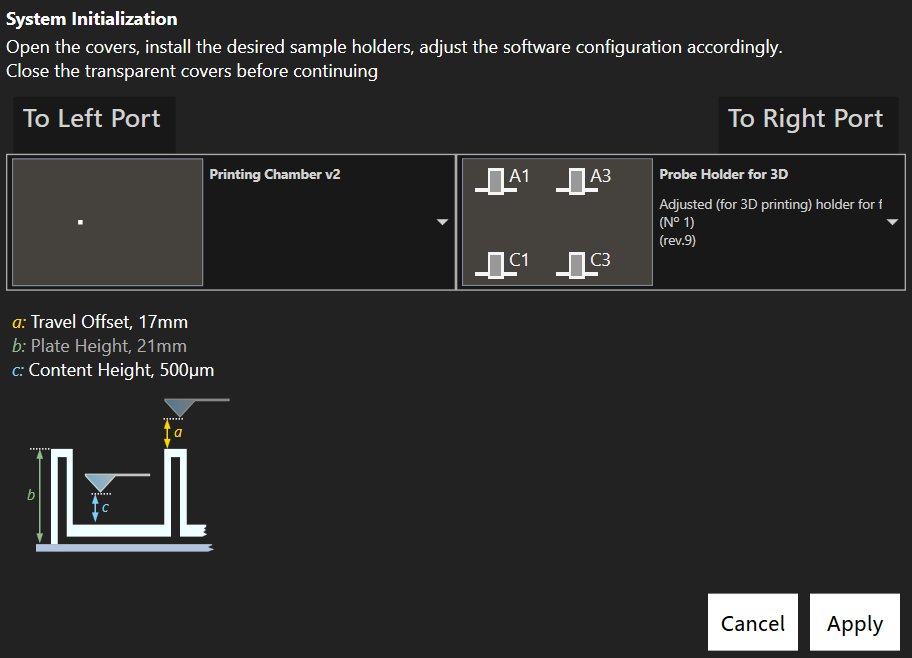
Then insert the desired plates and configure the system by selecting the
appropriate plate type. Press To Left Port or To Right Port to get access to
the plate holder from either sides. During this step, the Y axis is disabled and
can be freely moved by hand without disengaging.
The software at a glance
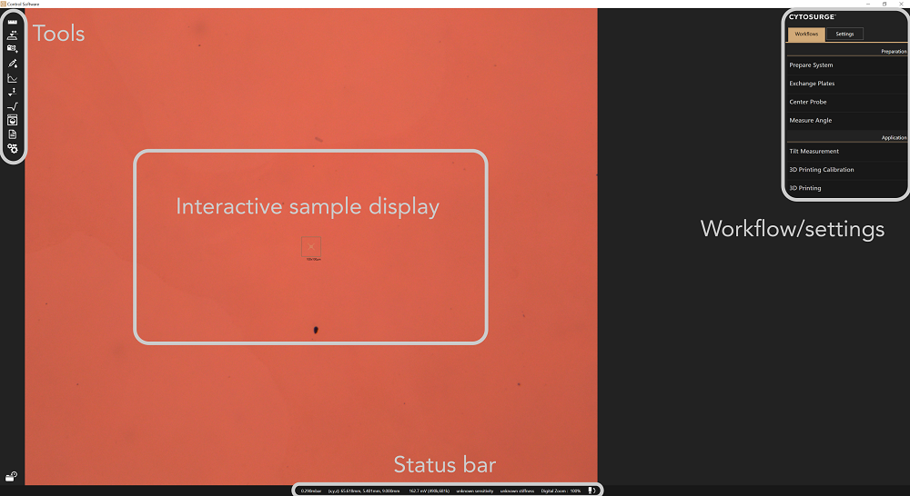
Interactive sample display
The main section of the program shows a live video feed from either of the
system cameras. The view can be changed at any time by pressing the camera
exchange symbol
 located
in the status bar.
located
in the status bar.
Software elements such as the crosshair or a structure preview are shown on the video feed depending on the context. The underlying sample can be moved by dragging on the screen with the mouse cursor.
Toolbar
Tools provides access to standalone components.
Workflows/Settings
Depending on the selected tab, application settings or a list of available workflows are shown. Each workflow consists of several individual steps, where parameters and options can be chosen as necessary.
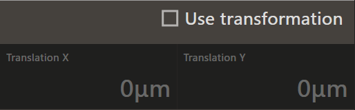
- Parameter
-
In tools, workflows and settings menus, parameters written in a bright, white font can be changed in an editor by simply touching or clicking them. In contrast, grey values are either in a blocked state or generally read-only and cannot be changed.
- Settings quick access
-
By pressing
Ctrl+Spacebar, a quick access to Digital Zoom, Illumination and Lens current sliders appears on top of the video feed display. WhileCtrlis held, sliders can be adjusted by scrolling the mouse wheel or clicking with the mouse cursor. PressingSpacebaragain switches to the next slider.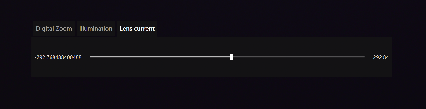
Status bar
At the bottom of the window, system status information is displayed, such as pressure applied, axes coordinates, laser signal, probe information and the camera switch button.
Media
Recorded media, such as screenshots, are stored in a database on the system computer. Already acquire media can be inspected by expanding the media bar. The data can later be accessed and/or exported into standard formats, e.g. for presentation purposes or further processing.
Where to go from here?
- Mount and configure a probe with the Prepare System workflow
- Insert the sample if not done so already with Exchange Plates
- Use the Navigation Tool to move across the sample
- Calibrate the pinpoint positioning feature to print a structure on a defined position on the substrate
- Print a structure once the system is ready
- Measure the substrate tilt compared to the horizontal plane or local surface topography