Mapping
This workflow maps a substrate onto which the print will be performed. The resulting map is a grid of points defined by the user at which the height of the substrate is measured by the iontip. This height map offers a higher spatial resolution than the Translate and rotate feature, whose resolution is limited by the optical resolution of the top view system. Using the mapping workflow the spatial resolution for placing an object is limited by the XY pitch of the measurement grid and the iontip shape and size.
Because of the pyramidal shape of the iontip, the highest resolution (< 1 μm) mapping is only possible on structures of a maximum height ~ 1 μm. The intended use case of high resolution mapping is conductive pads, lines and other structures obtained with standard lithography. Even for maps at lower spatial resolution, we do not recommend to use this feature to map structures with a height above 7 μm.
Prerequisites
The following steps must be validated to use the mapping workflow as a topological analysis tool:
- The substrate is thoroughly cleaned
- The whole system is accurately calibrated
- The Iontip Offset Calibration workflow is completed, assuring precise optical placement of the map
- The area in and around the region to map must be in general free to avoid collisions
Mapping on areas printed with Printing Solution bright [Cu]
Mapping of an area containing previously printed structures with Printing Solution bright [Cu] will result in clogging of the iontip.
Collision with previous structures
The iontip shape and size will influence the accessible areas for mapping. In case of out-of-plane structures already present on the substrate, please refer to this information to avoid collisions.
Mapping in a nutshell
To map an area of the substrate and place a structure precisely on the map perform the following steps:
- Using the top view system, bring the area to scan to the center of the screen.
- Depending on the substrate/ink combination, check the table below for the right potentiostat potential to apply during mapping.
- Enter the Mapping workflow and acquire a map as described below.
Note
After mapping it is advisable to flush the Iontip at a pressure of 100 mbar for 1 minute in a water well in order to remove contamination from the aperture.
- Use the Voxel Cloud Generator to plot the map and create a printfile with the determined start position as described below.
- Revert the potentiostat potential back to the original value.
- Print the file using the 3D Printing workflow.
The feature has the following characteristics:
| Parameter | Value | Limit |
|---|---|---|
| Tip lifetime (new iontip) | ~5000 points | Clogging of the aperture |
| Z resolution (high resolution mapping) | <0.25 μm, limited to 1 μm height | Z stage resolution, substrate cleanliness, iontip shape/size |
| XY resolution | <1 μm, limited to 1 μm height | Map resolution (user defined), iontip shape/size |
| Accuracy (map placement) | 2-6 μm | Optical resolution of top camera |
| Mapping potential, Au substrate | -0.5 V | - |
| Mapping potential, Cu substrate | -0.5 V | - |
Mapping workflow
The Mapping workflow uses the absolute coordinates from the XYZ axes. In both top and bottom system view, the map is centered around the absolute coordinate of the target point.
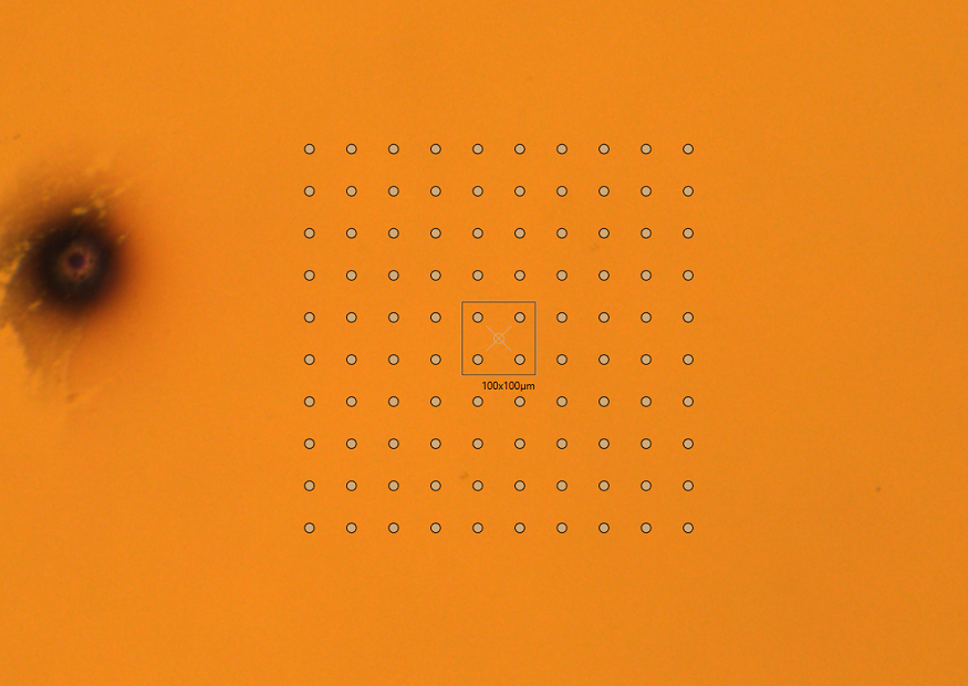
The grid points will be measured from bottom left to top right and a file with the
absolute coordinates measured at each contact point will be created in the
%USERPROFILE%\Documents\Exaddon\Substrate Maps subfolder.
First the positioning parameters are entered:
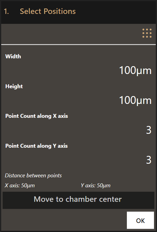
- Width and height of the area to scan
- Number of measurement points along the X axis
- Number of measurement points along the Y axis
Clicking Move to chamber center moves the top view to the center of the
printing chamber which usually corresponds to the center of the substrate.
Move the grid of points above the area to map using dragging and/or the
navigation tool. Click OK to move to the next step.
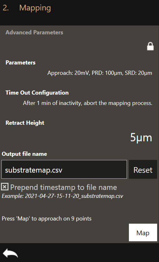
In this window you can define additional parameters for the mapping.
-
Parameters: The mapping parameters are similar to the parameters used for 3D printing. The same mechanism is used to map. An exhaustive description of each of these parameters is found below.
-
Time Out Configuration: If the mapping process comes to a halt, the system waits this specified amount of time before aborting.
-
Retract Height: The retract height is the distance to retract after the setpoint of a point has been reached.
Minimum retract height
The minimum retract height for mapping must be larger than the highest structure present on the substrate. This is necessary to avoid crashing the iontip.
- Output file name: Specify a custom file name for the result of the mapping workflow.
Set the right mapping parameters and click Map to start mapping. Once completed, use the Voxel Cloud Generator to visualize the map and place structures on it.
Parameters
Clicking on Parameters will open the Mapping Configuration dialog where the
mapping parameters can be set. The default values are loaded every time the
software is started.
This is the Mapping Configuration dialog:
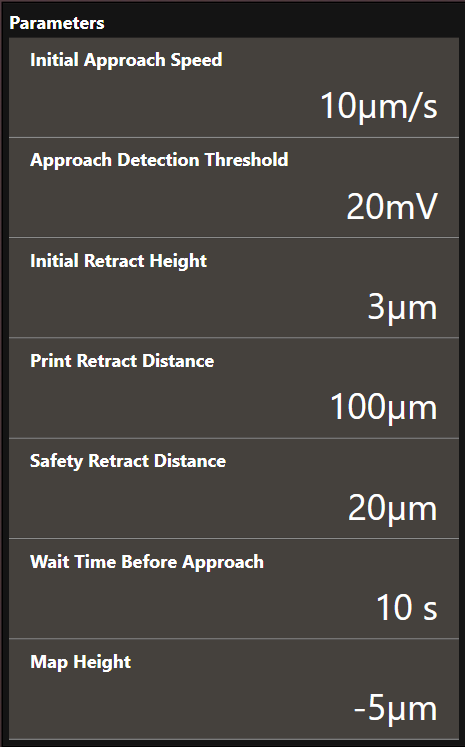
- Initial Approach Speed
- The approach speed of the cantilever at the start of the printing run. Maximum recommended speed is 20 µm/s.
- Approach Detection Threshold
- The cantilever deflection setpoint in Volts that has to be reached when the system first approaches the substrate to map.
- Initial Retract Height
- After the iontip has reached the substrate surface at it retracts the distance specified here and continues to the first mapping point travelling at the defined height above the substrate surface.
- Print Retract Distance
- To avoid collisions when moving from one print structure to the next one, this distance is added to the currently defined content height when moving to the start position of the next print structure.
- Safety Retract Distance
- The distance to retract after a print structure has been printed. This helps to mitigate collisions with already printed structures.
- Wait Time Before Approach
- The time to wait after 0 mbar has been applied but before the approach starts. This prevents false deflection detections as the iontip might still oscillate during the approach if no wait time is used.
- Map Height
- Mapping uses an ad-hoc print file to approach at each position. This parameter defines how far the print file is positioned below the surface. The surface is defined at the first approach. The map height should be below any point on the surface you are mapping.
Map visualization and printfile creation
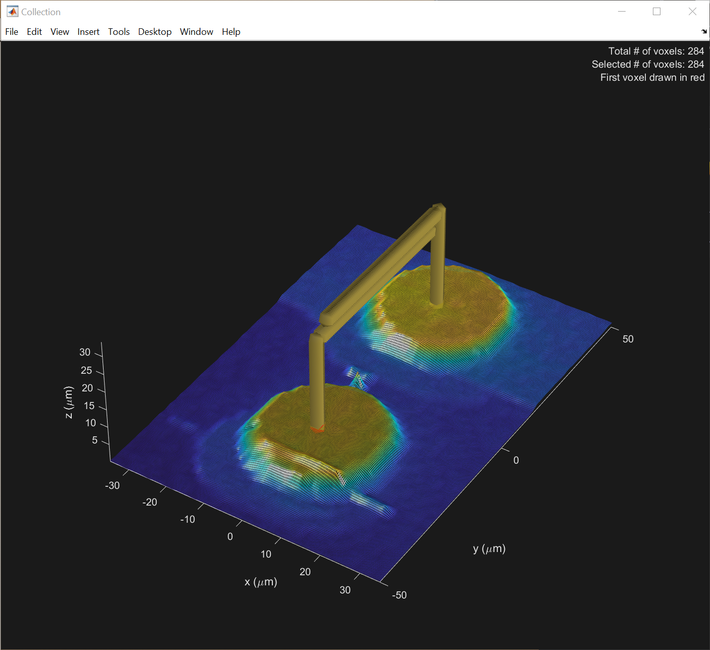
After a substrate map has been acquired it can be visualized using the Voxel Cloud Generator.
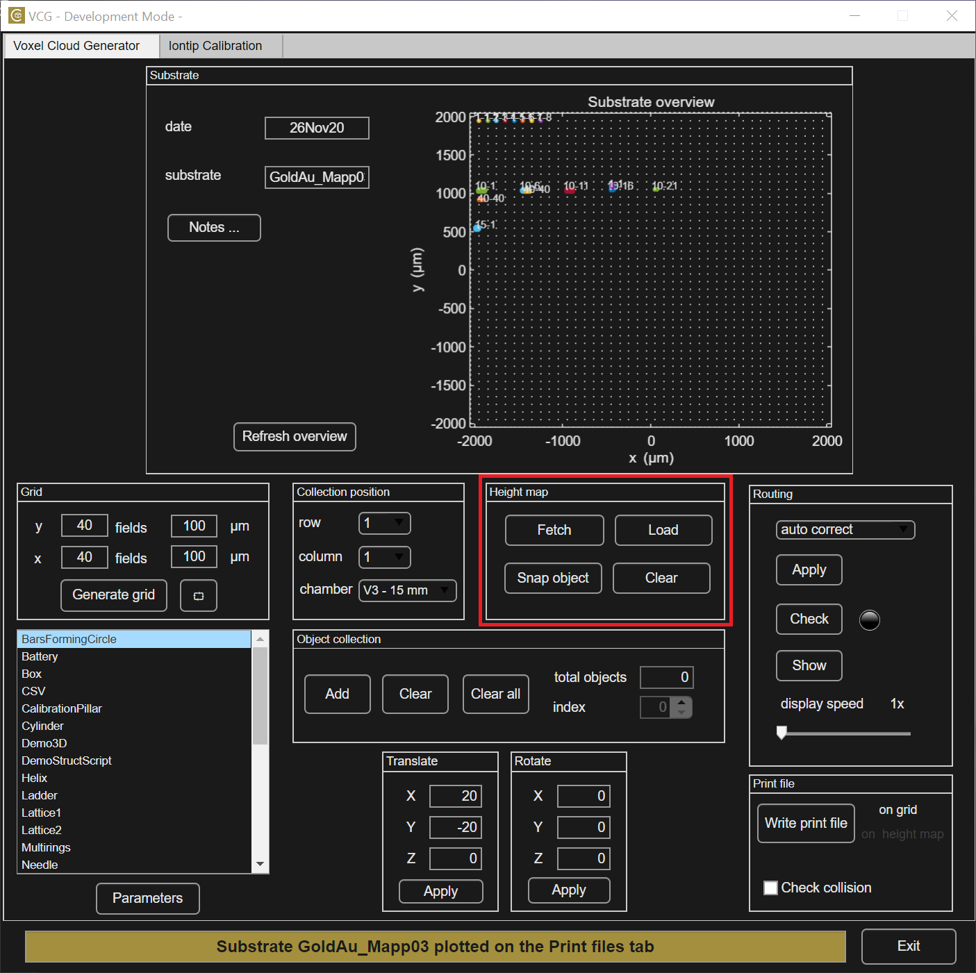
By clicking the Fetch button the maps will be moved to the current substrate folder. After this, the map file can be loaded using Load.
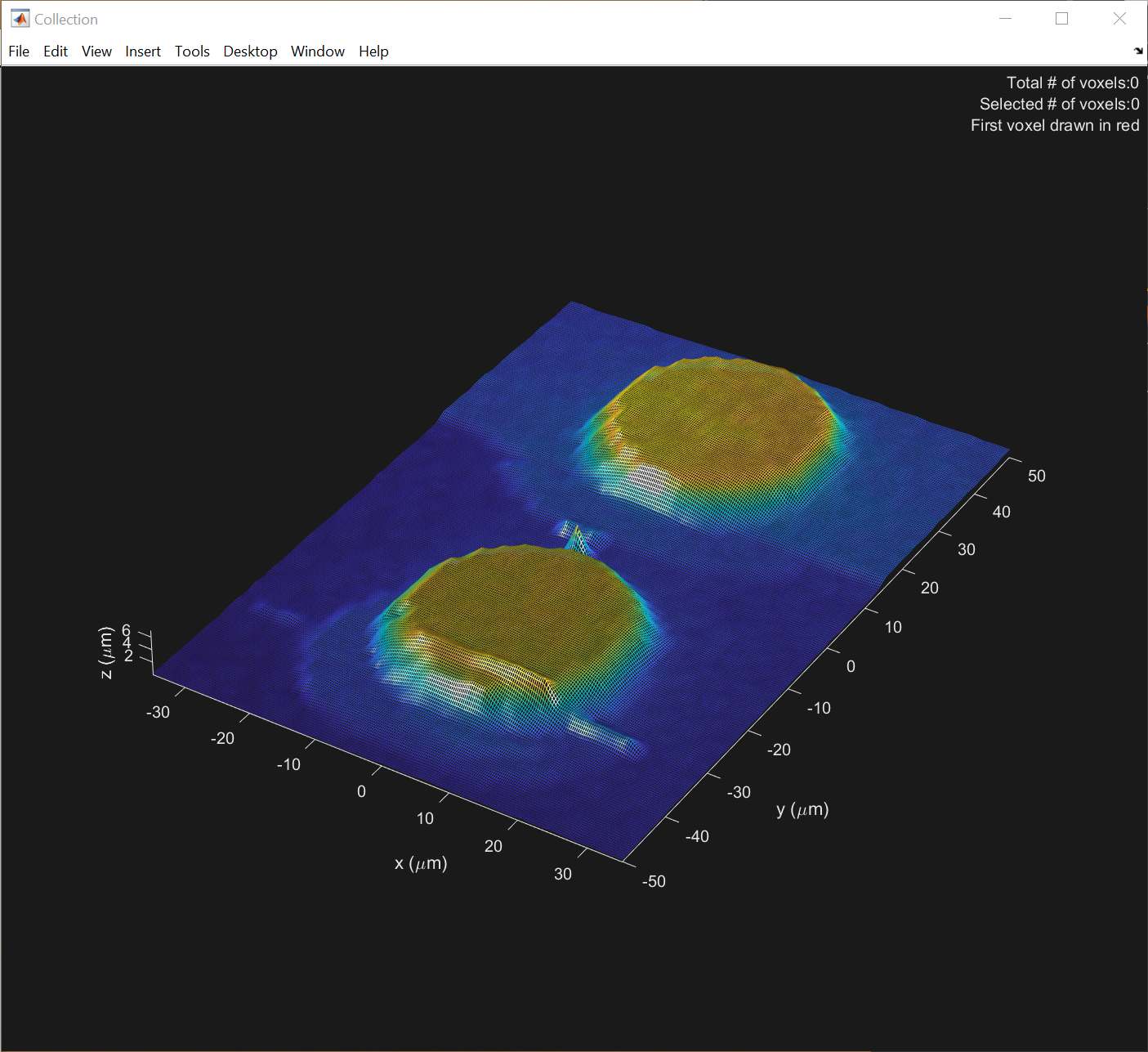
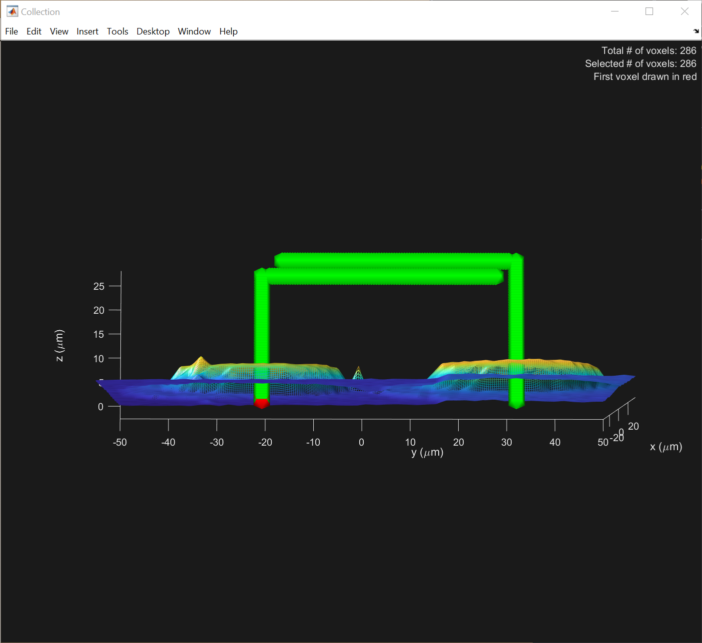
The map will be visualized in the collection figure. Place a structure on the map as normally done with the VCG. The structure can be snapped to the current map height by pressing Snap object, as shown below.
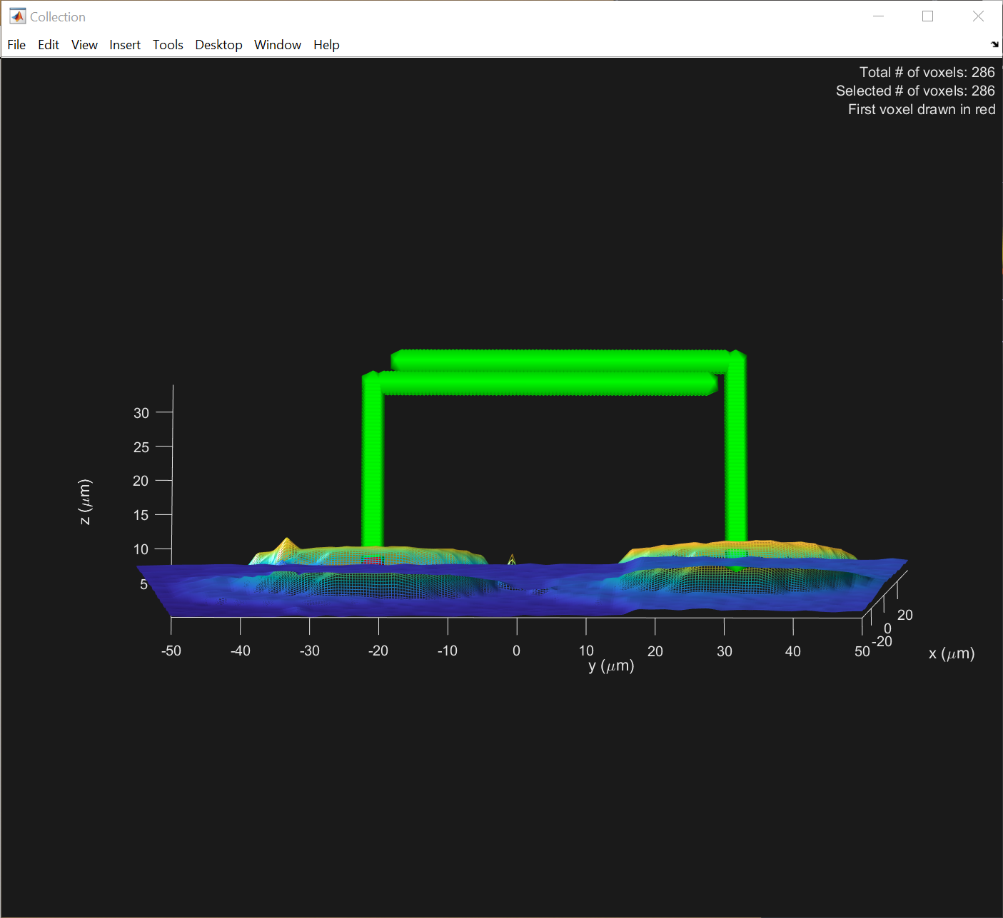
The printfile is now ready to be generated by pressing Write print file. The software should display “on height map”. By loading this printfile in the 3D Printing workflow the structure is printed in the exact location indicated by the map.
Warning
It might be necessary to perform calibration of the Iontip with the tip calibration app before performing the print, as contaminants collected during mapping might influence the iontip pressure-diameter relationship.