3D Printing
Prerequisites
It is mandatory to successfully execute the following workflows before starting a print:
Additionally, the tip position can be calibrated using the Iontip Offset Calibration. This calibration is required for printing on existing structures.
Windows updates
It is recommended to install any windows updates before starting a print, or the computer might reboot unexpectedly resulting in sample loss.
Printing in a nutshell
Navigate to the 3D printing workflow:
- Set the right configuration options
- Add at least one print file to the Print List
- Optionally translate and rotate files
- Optionally check for collisions
- Check if you want the 3D view present when the printing starts
- Start printing
Configuration options
Advanced Parameters
The Advanced Parameters are only available after clicking on the lock icon. The Advanced Parameters should only be used after instruction or special training by Exaddon Customer Support. These parameters are therefore not explained here.
Parameters
Clicking on Parameters will open a dialog in which the standard parameters for the
printing can be set. All changes are lost every time the software is closed.
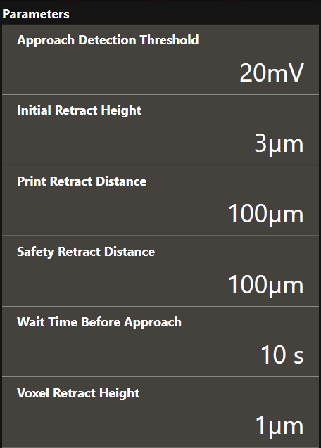
- Approach Detection Threshold
- The cantilever deflection setpoint in Volts that has to be reached when the system first approaches the sample before printing. The iontip will approach the sample at (X0, Y0). If the Approach Detection Threshold has been reached, the software defines the current z-position as Z0.
- Initial Retract Height
- After the iontip has reached the substrate surface at (X0, Y0, Z0) it retracts the distance specified here and continues to the first voxel location at (X1, Y1) travelling at the Initial Retract Height above the substrate surface (=Z0).
- Print Retract Distance
- To avoid collision when moving from one print structure to the next one, the iontip is retracted from the substrate surface by this distance before laterally moving to the start position of the next structure.
- Safety Retract Distance
- The iontip retracts by this distance after a print structure has been completed. This helps preventing collisions with already printed structures. When an idle pressure above 0 mbar is used, raising this distance can prevent unwanted plating as well as iontip clogging after a print structure is completed.
- Wait Time Before Approach
- The time to wait after 0 mbar has been applied but before the approach starts. This prevents false deflection detections as the chamber solution may not have settled down before the approach.
- Voxel Retract Height
- The distance by which the iontip retracts from a voxel each time a voxel has been completed. 1µm is recommended for standard 3D printing.
Time Out Configuration
If the printing process comes to a halt, the system waits the specified amount of time before executing a time-out action. You can choose one of the following actions:
- Abort the whole printing process
- Pause the printing process
- Cancel printing the current structure and continue with the next one
- Cancel printing the current structure and pause the printing process
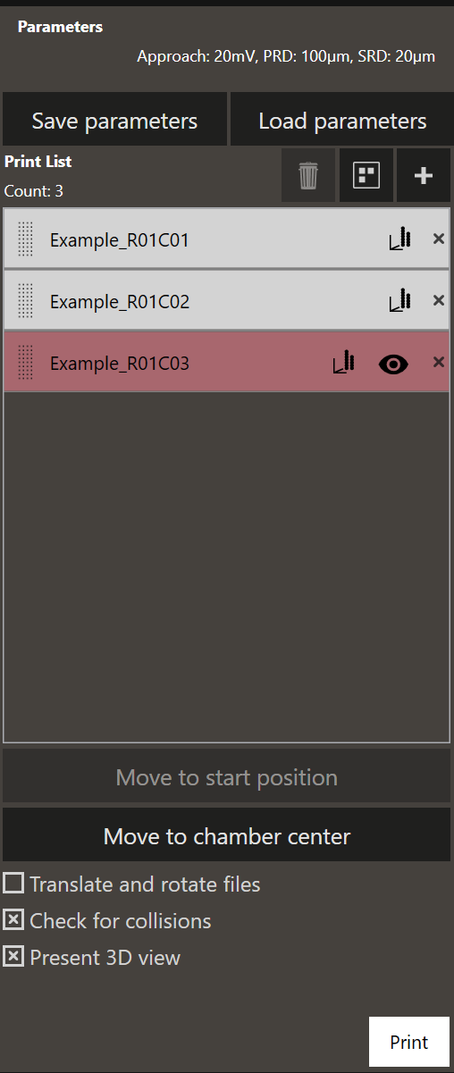
Add print files
Clicking on + opens up a file selection dialog. You can add any number of
print files.
Click and drag the dotted area left of the print file name tag to reorder manually. Clicking on the graph icon on the right of the file name tag gives a 3D visualization of the voxels in the print file.
Move to start position
Moves the top view system to the start position of the currently selected print file.
Move to chamber center
Moves the printing chamber center underneath the top view system. This center is usually also the center of the printing substrate.
Translate and rotate files
Apply a transformation (translation and rotation) to each file. This allows you to reposition a print file to any position within the accessible area of the substrate.
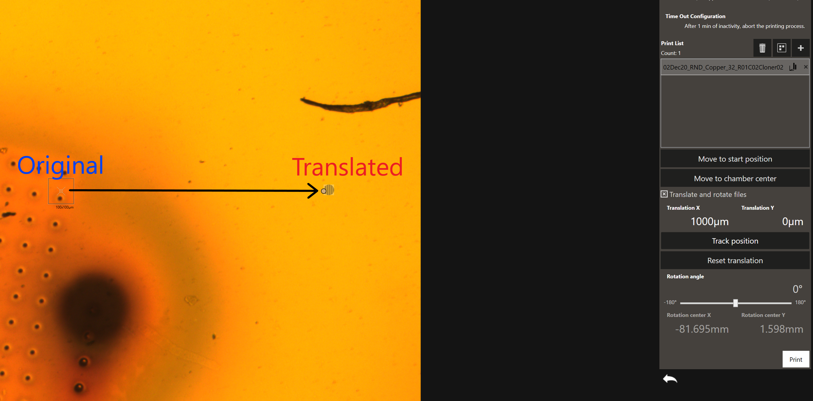
Using the Translate and rotate files feature structures can be precisely placed onto the substrate. This is particularly useful if the substrate contains existing features, such as conductive lines, onto which should be printed.
To precisely place a structure with this feature, the iontip position with respect to the top view system needs to be calibrated using the Iontip Offset Calibration workflow.
The structures can be moved either by translating by specific amounts, or by clicking on Track Position and dragging on the screen.
The precision achievable with this method is around 3 to 6 μm. For higher accuracy (~ 1 μm) the Mapping workflow can be used.
Collision checker
The collision checker makes sure that a print file can be printed without the cantilever colliding with another printed structure. The collision checker is by default disabled; it can be enabled by clicking on the “collision checker” checkbox in the 3D Printing workflow. When the collision checker is enabled, it starts checking from all print files, starting at the top of the print file list. The file that is currently being checked is marked light blue. The collision checkers checks for collisions with already printed structures (the content of the print history list), and with structures-to-printed that are higher up in the print files list. In case a print file was not or not completely printed, the collision checker recalculates. Please note that in case of rotation of the printing files, the collision checker is disabled.
When two files collide, the one that will cause a crash is marked in red and the print file will not be printed. Check the screenshot below:
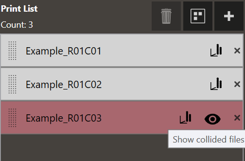
Collision checker requires accurate print history
The collision checker checks against all files currently in the print history list. Therefore, the list must be complete and up-to-date. Print files printed on previous substrates must be deleted from the print history list by the operator, either manually or upon closing/opening CAPA. Conversely, deleting structures from the print history list that are still on the substrate-under-print makes the collision checker ignore them.
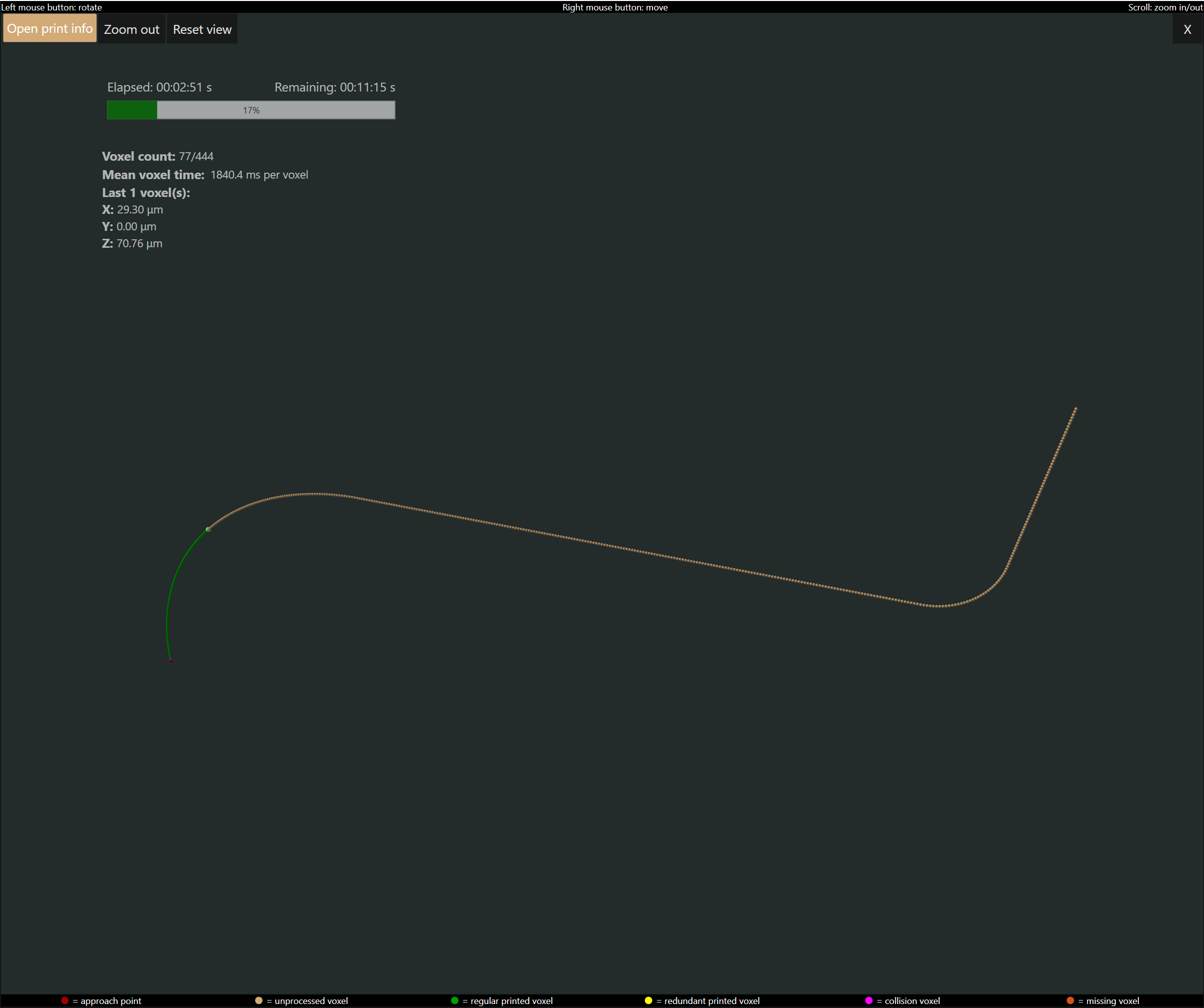
3D live view
The live view shows the printing progress in real time. On the live view, the structure is represented as a set of voxels that will be printed. A big sphere is present at the position of the current voxel that is supposed to be printed next. As the print progresses, the colour of the represented voxels changes. The displayed voxel colour depends on its printing status: green if the voxel is printed in a regular way, yellow if in a redundant way, or purple if a collision voxel was detected. On the live view window, one can find meaningful information. The live view shows the elapsed time and the estimated remaining time of the print. The current voxel count, the mean voxel time, the time required for printing the latest voxel/s are also presented. The X, Y and Z axis positions of the voxel that is currently being printed are shown.
Start printing
Clicking Print will immediately start the printing run. The printing can be
started at any iontip position and continues until the last print file in
the print list has been printed.
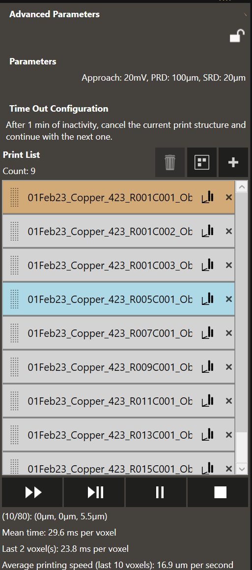
Progress monitoring
The progress monitor contains several items:
To remove a print file from the print list, click on the X mark on the right of a file name tag. Print files can be also added to the print list when printing is in progress.
To change the order of the print files, click on the dotted area of a print file entry and drag it to the desired position.
The four controls displayed at the bottom of the dialog will (from left to right):
- Skip a file and continue with the next
- Pause and abort current
- Pause after current
- Abort printing
While printing is paused, the parameters and time out configuration can be changed.
At the top right the estimated remaining print time is shown.
At the bottom, the current voxel and the total amount of voxels in the current print file. Voxel 10 out of a total 80 voxels is being printed in this example. The location (x, y, z) of the active voxel and the mean time which is calculated over the already printed voxels is presented. The last voxel duration is shown as well. In case the voxel print duration was very short, the aggregated printing time of multiple voxels is displayed.
Note
The Z coordinate of the active voxel gives valuable information about the iontip - sample separation. If the system does not print, it could be that the Z coordinate specified in the .csv file is incorrect. It should be very close (few 100 nm to max. a few µm from the surface).
When 10 consecutive voxels are printed at the same location on the x and y axis, the average printing speed of the last 10 voxels is shown. Typical speeds are 1 to 1.5 µm/s.
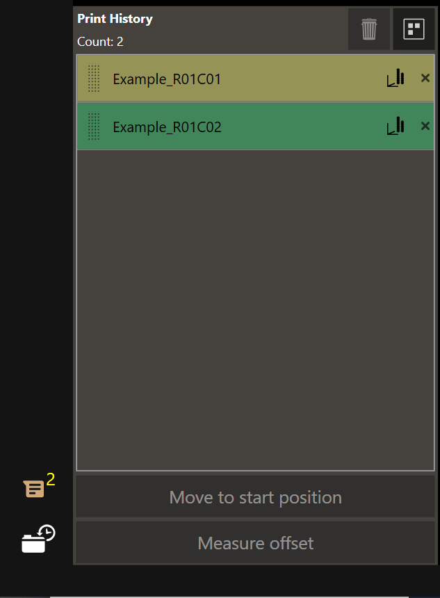
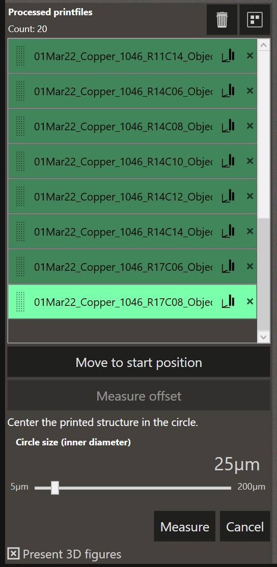
Print history
Once a file has been printed or the print process is aborted, the file is moved to the print History. This is a collapsable list found at the bottom left of the screen.
- The number of processed files is indicated in the icon
- The currently selected file is highlighted
-
Files are color coded based on the result of the printing process
- Green: the file has been successfully printed
- Yellow: the printing process has been aborted or timed out.
- Red: The printing process did not complete due to an error.
The voxel coordinates in these files are used to compute the new content height of the printing chamber (see Exchange Plates). This helps to avoid unwanted collisions after printing tall structures. It is the responsibility of the operator to clear the print history list when a new substrate is loaded into the printing chamber. Clearing the list will reset the content height to the original value and it will stop the collision checker from checking against the cleared files.
3D view dialog
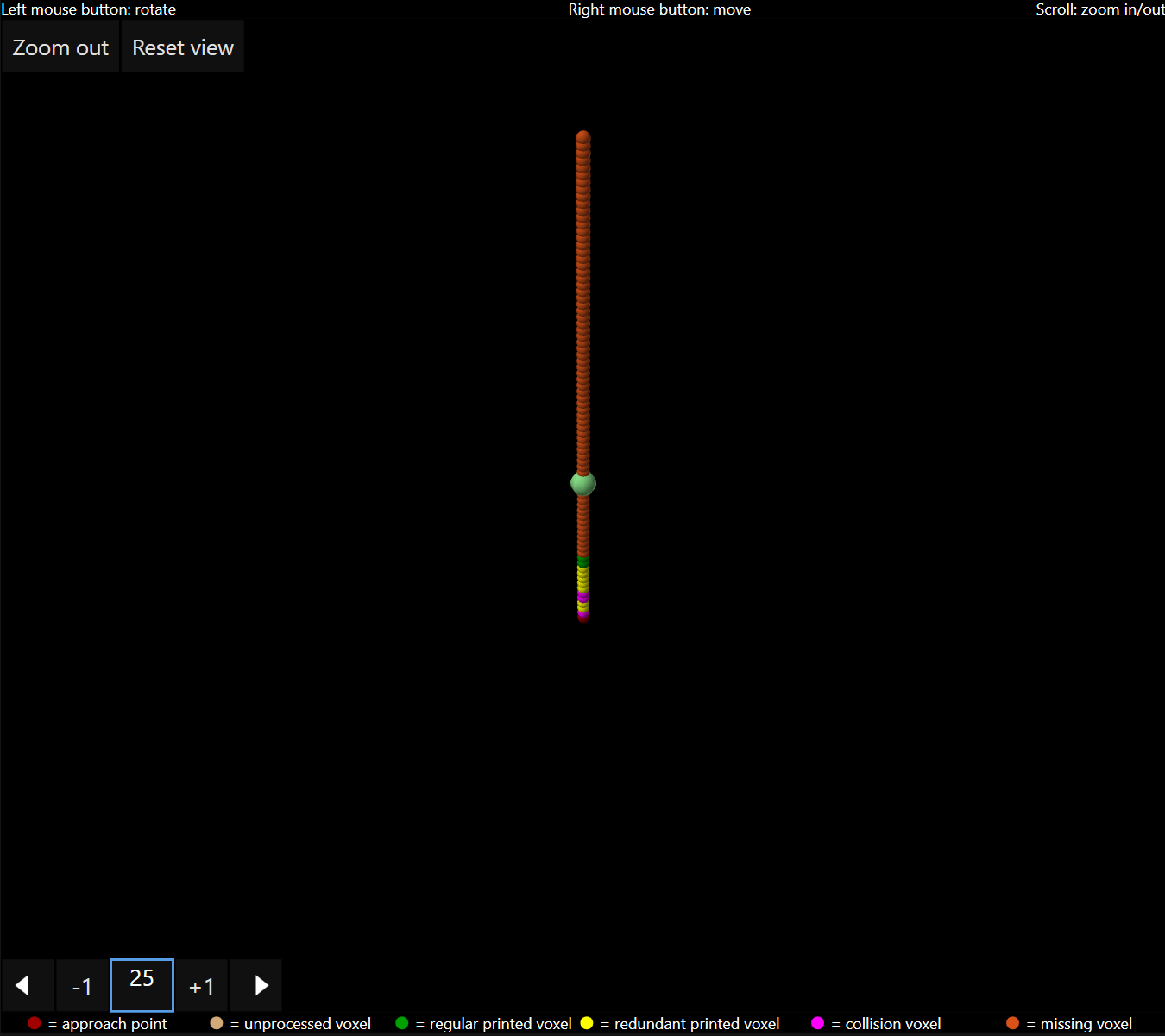
The 3D view dialog is available in the print file list and in the print history list. Clicking the graph icon visible in each file name tag, displays a dialog box with a 3D rendering of the design. The dialog box contains a “play tool” to display the printing sequence of the voxels. The play tool is working before and after printing a file. Clicking the arrow pointing left shows the voxel printing sequence in reverse.
Log Files
The workflow produces three different log files per print file. All files are
saved to %USERPROFILE%/Documents/Exaddon/Print Data.
The information contained in the log files can be accessed with the Log Viewer
Iontip Offset Calibration
This calibration is necessary to align the iontip position, which changes from tip to tip, with the center of the top view system. It is performed by aligning the position of a printed pillar with center of the screen.
- Open the print history and click on a desired structure.
- Select
Measure offset.
- Measure the offset by dragging on the video feed to align the center of the video feed on the structure.
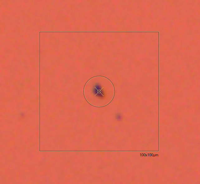
- Click
Measure. The offset is shown. - Click
Yes. The measured offset will be automatically applied to all future print runs.