Designing a printfile
The page serves as a general guideline to design a printfile using the Voxel Cloud Generator. This is a general approach and should be considered only a starting point for your own experimentation and investigation.
Designing line structures
Line structures are constructed by a line of voxels.
-
Input parameters
- line thickness
-
Output parameters
- v (voxel distance)
- P (pressure)
To design a printfile, use the following workflow:
- Pick a line thickness
- The thickness will depend on the desired smallest feature size
- Under normal conditions, the voxel height v is always 0.5 μm
- Select the correct pressure for the desired line thickness in the tip using the tip calibration app
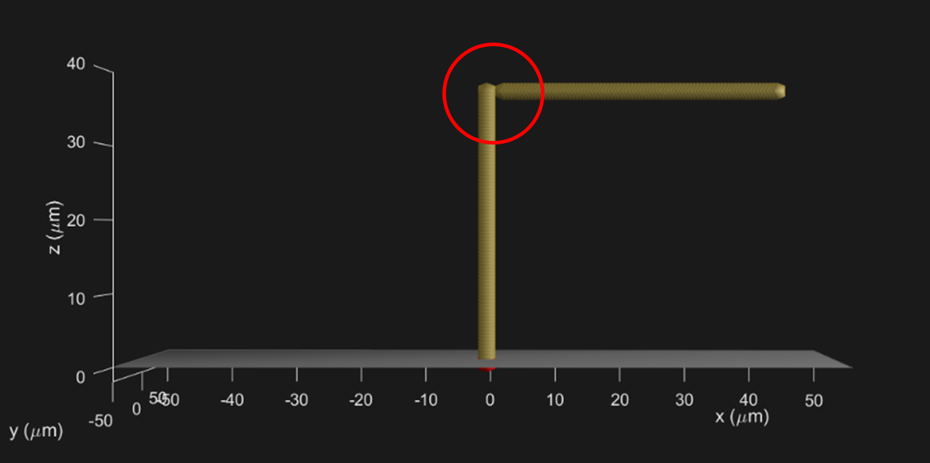
Note that when merging two different lines some space (2 μm) should be left between them to avoid skipping voxels due to secondary deposition (spray). An example is shown below.
Designing larger structures
General approach: strand printing
Building solid objects from a growing metal surface can be achieved in a variety of ways. However, not all these result in high quality and reproducible printed structures.
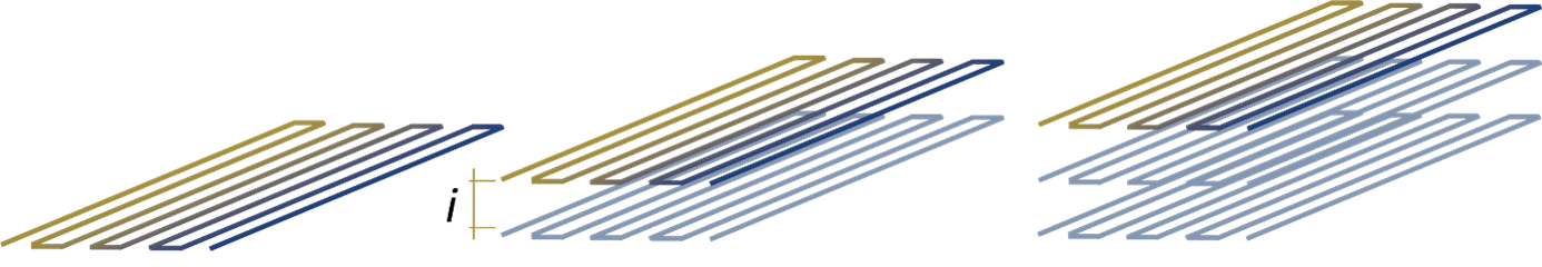
The most effective way to create a three-dimensional object is to fill the volume with a continuous strand of metal. For example, when building a wall, one should build a series of horizontal lines stacked on top of each other, as shown below.
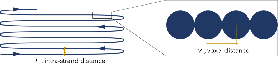
In this way, the metal grows primarily from the voxel that was just printed rather then from the metal of the strand below the tip. To favour the growth of the metal in this fashion one needs to select proper values for the intra-strand distance, i, and the voxel distance, v.
Standard values for printing speed, s, voxel distance, v, and intra-strand distance, i, are shown in the table below. Each set of values is dictated by the selected printing quality (smooth, balanced, coarse).
| Quality | s [µm/s] | v [µm] | i [µm] |
|---|---|---|---|
| Smooth | 1 | 0.5 | 2 |
| Balanced | 1.5 | 1 | 2 |
| Coarse | 2 | 1.5 | 3 |
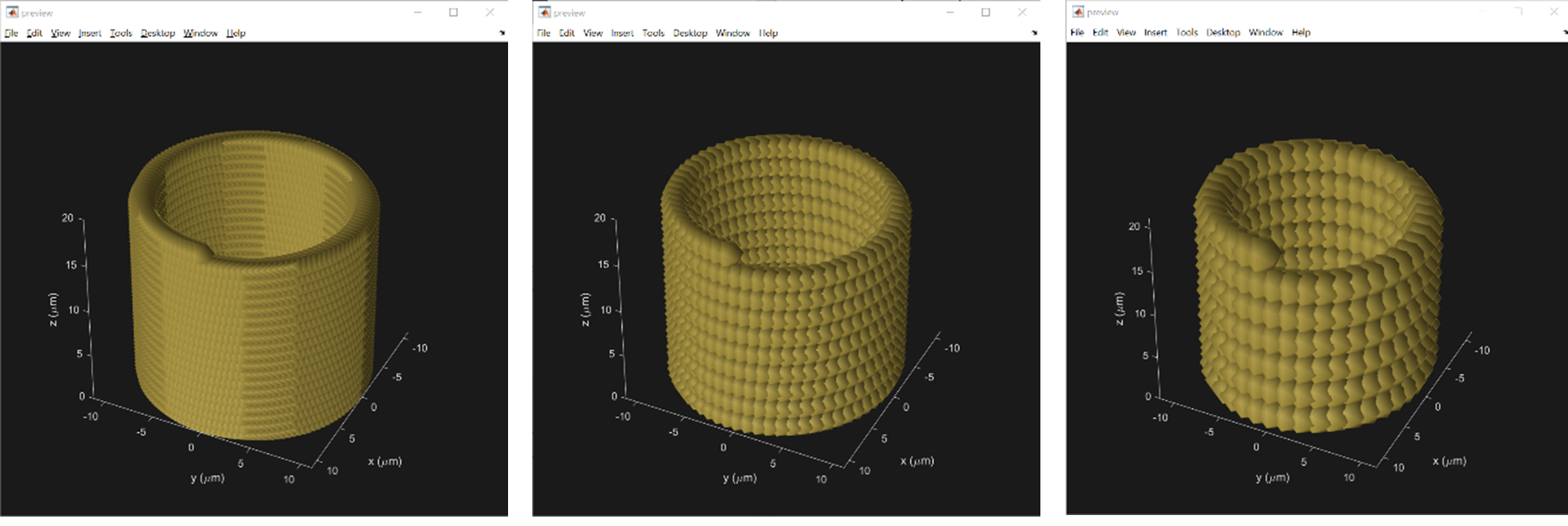
Designing hollow structures
Hollow structures are defined by a one voxel thick wall and are empty on the inside. For examples, walls, hollow cylinders, hollow cones etc (see below).
-
Input parameters
- quality (smooth, balanced, coarse)
- wall thickness
-
Output parameters
- s (saturation pressure)
- v (voxel distance)
- i (strand pitch)
- P (pressure)
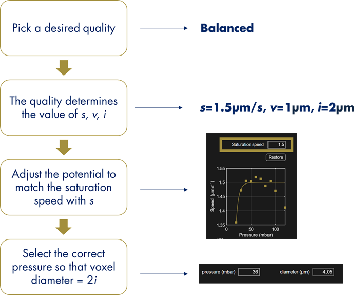
To design a printfile, use the following workflow:
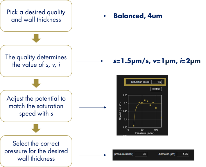
- Pick a desired quality and wall thickness
- The quality will depend on the desired smallest feature size and desired surface roughness
- The quality determines the value of s, v, i
- Use the table above to find the values
- Adjust the potential to reach the correct speed
- Print a calibration pillar
- The maximum speed is the saturation speed
- Adjust the potential to match it with the value of s
- Select the correct pressure for the desired wall thickness
Below an examples of a cylinder designed using three different quality settings: smooth (left), balanced (center) and coarse (right).
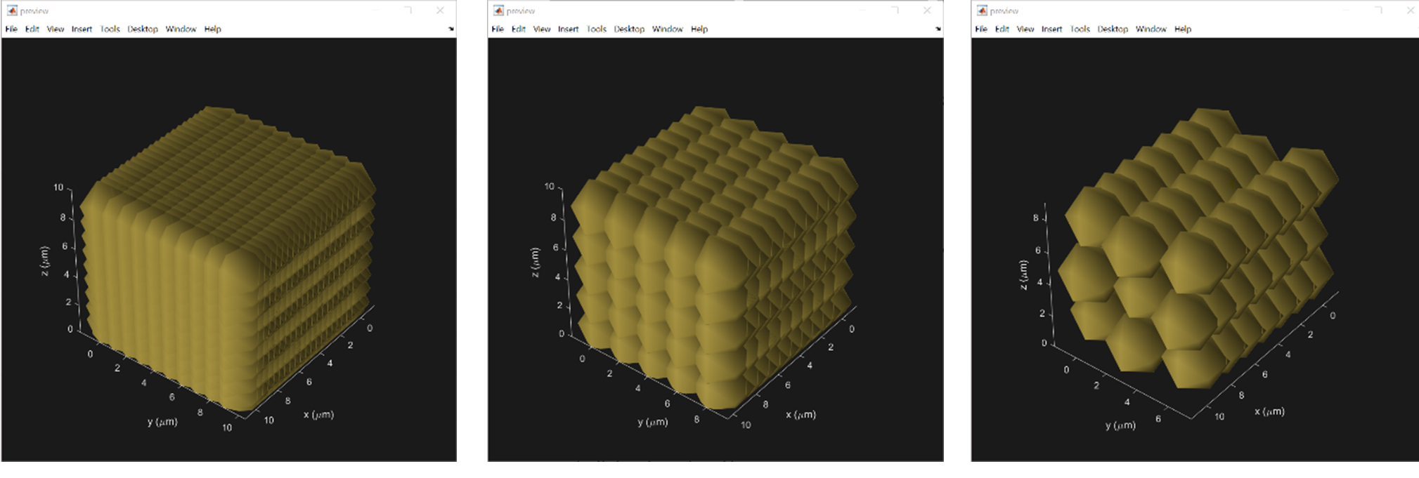
Designing fully metalized structures
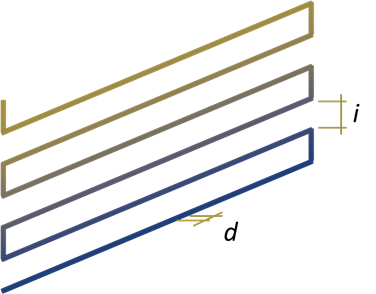
The same basic approach is used in designing fully metalized structures. In this case each layer is built following the same approach as before. The distance between layers is equal to the intra-strand distance, i, while the voxel diameter must be set equal to 2i (see the image below).
-
Input parameters
- quality (smooth, balanced, coarse)
- wall thickness
-
Output parameters
- s (saturation pressure)
- v (voxel distance)
- i (strand pitch)
- P (pressure)
To design a printfile, use the following workflow:
- Pick a desired quality and wall thickness
- The quality will depend on the desired smallest feature size and desired surface roughness
- The quality determines the value of s, v, i
- Use the table above to find the values
- Adjust the potential to reach the correct speed
- Print a calibration pillar
- The maximum speed is the saturation speed
- Adjust the potential to match it with the value of s
- Select the correct pressure to have a voxel diameter = 2i
Below examples of a cube designed using three different quality settings: smooth (left), balanced (center) and coarse (right).
Feasibility check
After the design is complete, a feasibility check must be performed. This is about system limitations and geometrical limitations as well. Some elements of the design need to be compared to the system specifications described in the general and ink specific design rules as follows:
| Design value | System spec to compare it to |
|---|---|
| Feature size (e.g. wall thickness) | Voxel diameter |
| Total structure volume | Printable volume |
| Total number of voxels | Printable voxels |
| Printing Speed | Printing speed |
| Overhangs | Maximum Overhang Length Maximum Overhang Angle Max. Aspect Ratio (overhang) |
- If all green: the print is feasible
- If some red: not feasible as it is
- If some orange: feasibility may need additional investigation/optimization on a case-by-case basis
Routing
Routing hollow structures should follow a layer-by-layer approach.
When routing fully metalized structures a similar approach can be followed.
For complex structures combining multiple objects, the following approaches can be used:
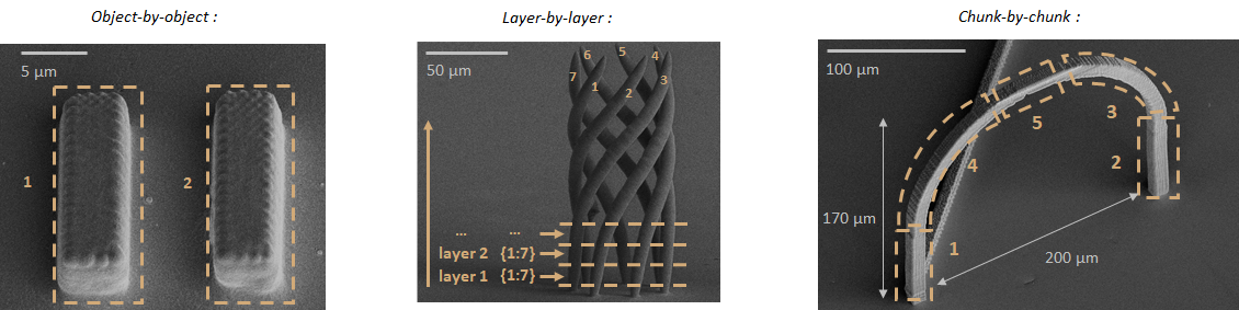
Three routings are possible for a given structure design:
- Object-by-object, where each element of the design is printed individually.
- Layer-by-layer, where each layer of voxels of the same Z level are printed one after each other, building all objects at the same time.
- Chunk-by-chunk, where blocks (or chunks) of the structure are printed one after each other taking into account the clearance rules to define the size and order of the chunks. This must be implemented manually in the generated printfile or script. It has the advantage to greatly reduce the movement in-between voxels and spare printing time but will likely create seams at each junction.