Design Rules
Design rules are guidelines giving an overview of the capabilities and limitations of the system.
Important
Not following those rules might leads to:
- Accelerated wear of the consumable.
- Tip breaking or clogging.
- Crushed or bent printed structure.
- Inconsistency and unreliability of the tip calibration.
- Decreased efficiency and speed of the printing process.
- Decreased resolution and quality of the printed structures.
When not otherwise specified, process values are taken referring to Exaddon’s printing solution Cu bright.
Printing chamber and printing area
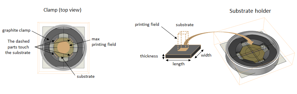
The shape of the consumable and the printing chamber result in a limited reachable area. Printing chambers specifications about the usable samples and reachable area are found here. To use a larger area or specific samples, a custom printing chamber must be built and its plate definition has to be added to the printer.
Printing chamber V3
| Parameters | Range | |
|---|---|---|
| Allowed substrate size | Small substrates | Large substrates |
| Length (mm) | 14.6 - 15.3 | 24 - 25 |
| Width (mm) | 14.6 - 15.3 | 24 - 25 |
| Thickness (mm) | 0.3 - 3.4 | 0.3 - 3.4 |
| Printing field size (X-Y-Z) | Ø ~ 8 mm | Ø ~ 16mm |
The clamp sits on top of the substrate holder and mechanically pushes the substrate down. The clamp also makes electrical contact as it is made of conductive graphite that is pushing on the substrate at four positions indicated by arrows.
Placing the structure on the substrate
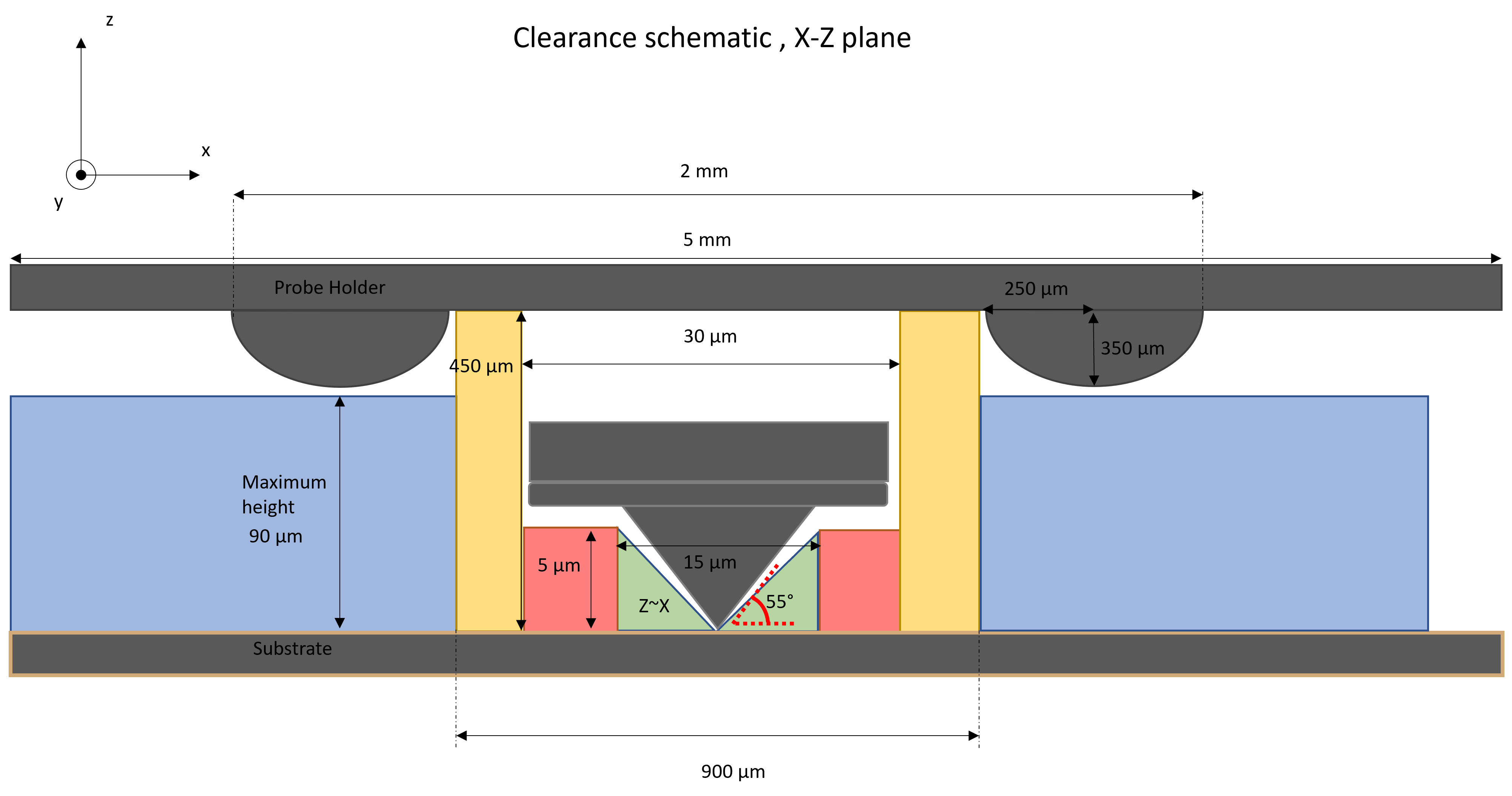
Clearance
To safely place printfiles on the substrate one needs to consider the shape of the iontip. This shape can cause collisions with structures that are already present on the substrate. As a general rule, always print in a left-to-right, top to bottom order to maximize the available clearance under the iontip.
To aid the placement of tall structures, please take into account the safe heights indicated in the following table:
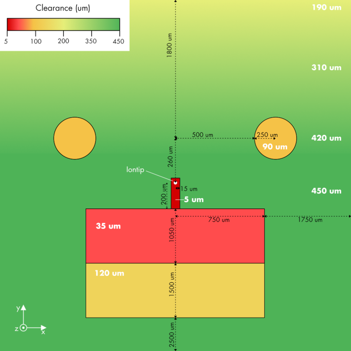
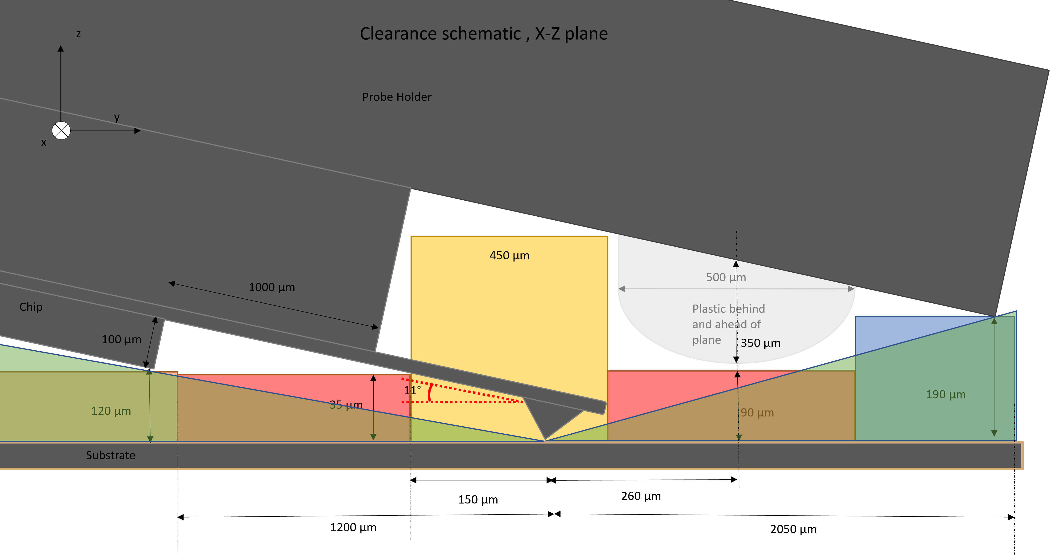
Clearance over the whole substrate (excl. cantilever)
| Location | Clearance [µm] |
|---|---|
| Anywhere | 35 |
| Anywhere sideways (along ± X) | 90 |
| Anywhere upwards (along + Y) | 190 |
| Sideways (along ± X), for specific positions | 450 |
| Upwards (along + Y), for specific positions | 450 |
To better visualize where the limits indicated in the tables stem from, please refer to the following map. Here is shown the clearance height (color coded) under the iontip. Distances are taken from the aperture.
To aid the understanding of the map, the following views of the iontip (front and side respectively) can be used.
Additionally, you can toggle a collision check in the VCG.
Warning
There is a risk of damaging a previously printed high structure when moving the iontip into the printing chamber after printing a tall structure. To avoid this, observe the clearance rules above and set the content height of the printing chamber (see the exchange plates workflow) higher than the height of any structure on the substrate. The VCG assumes that the content height is set correctly and does not detect this kind of collision.
Alignment accuracy
Objects can be placed on existing structures on the substrate using the top camera or by mapping the substrate.
| Alignment method | Accuracy [µm] |
|---|---|
| Optical (top camera) | ~ 4 |
| Mapping | < 1 |
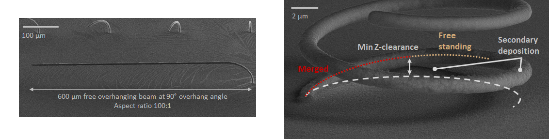
Overhangs and free-standing structures
The system can print overhanging structures and free-standing structures with little to no additional supports needed. The length limit of overhang structures is influenced by the stiffness (spring constant) of the free-standing structure being printed. Soft structures will hinder proper voxel detection.
| Parameters | Typical Value |
|---|---|
| Maximum overhang angle | 100° |
| Maximum overhang length | 150 µm |
| Maximum aspect ratio (overhang) | 50:1 |
| Minimum vertical distance between objects | ~2 µm |
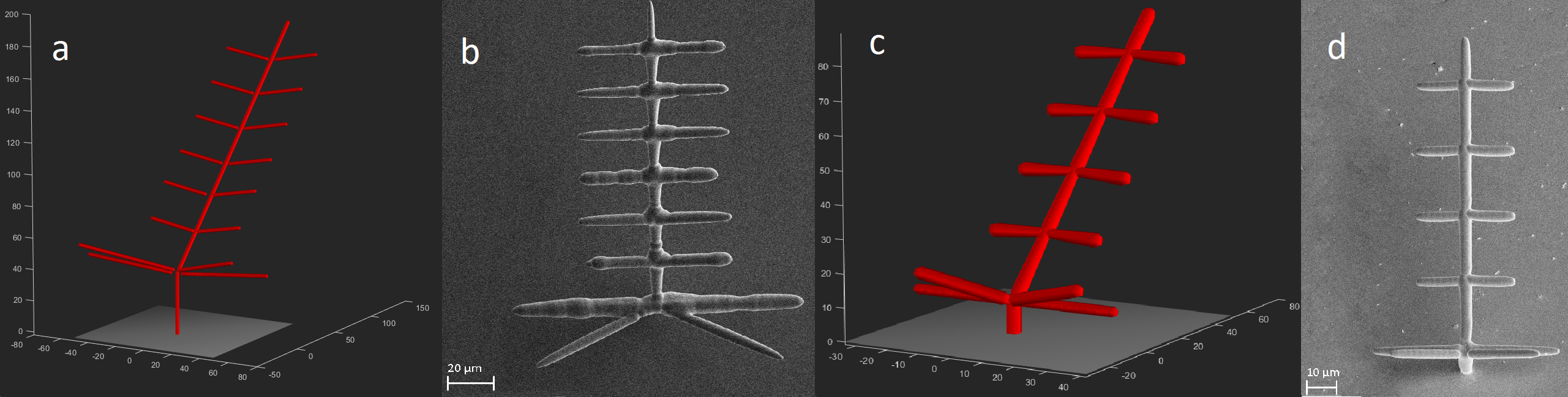
Secondary deposition
The secondary deposition also called “spray”, occurs on surfaces around where the system is printing and depends on the printing conditions. Spray increases the final diameter of a voxel, helps to smooth the surface or, in some cases, lowers the surface quality. the spray is created by the deposition of metal ions diffusing away from the tip. Spray intensity and radius scale mainly with the pressure applied.
If the spray effect is too strong for a given geometry, it can be compensated by reducing their printing pressure, and therefore the base diameter of the voxels affected.
in the example below (a), spray deforms the structure at the joins and the long horizontal beams (b). This effect can be compensated by modulating the pressure ( c). The resulting structure is more regular after printing (d).