Printing Head Maintenance
Maintenance and servicing may require the manipulation of the head mounted on the Z stage. Listed below are the different workflows and manipulations on the head which a trained operator will need to perform.
Note
Depending on your nose configuration (sealing screw or silicon tube), some of the workflows below will be different. Make sure to read the instructions adapted to your hardware configuration.
Hardware configuration
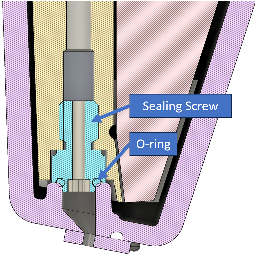
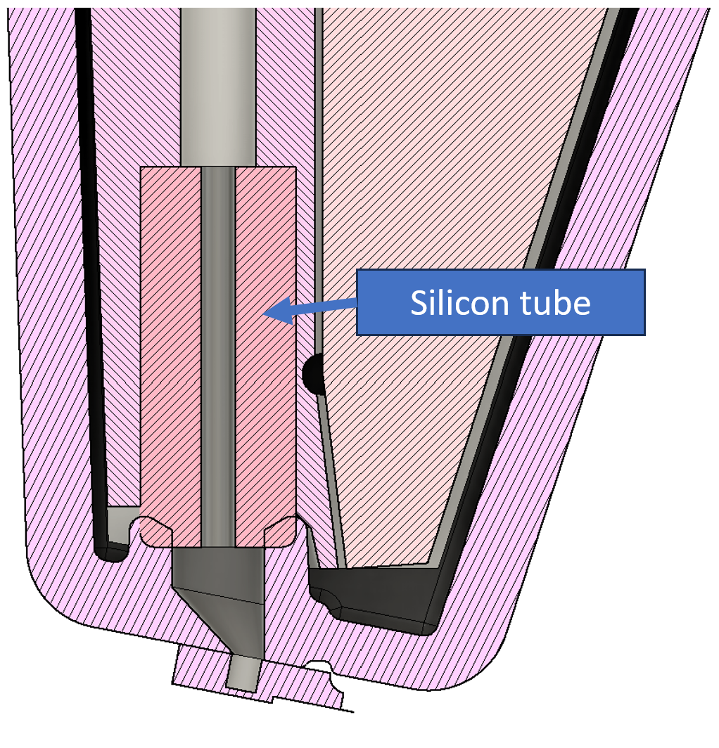
There are two different head configuration available, which differ by their nose sealing method: sealing screw or silicon tube. The sealing screw configuration uses a screw and an O-ring to seal the nose, while the silicon tube configuration uses a soft silicon tube to create the seal.
Sealing screw configuration:
Silicon tube configuration:
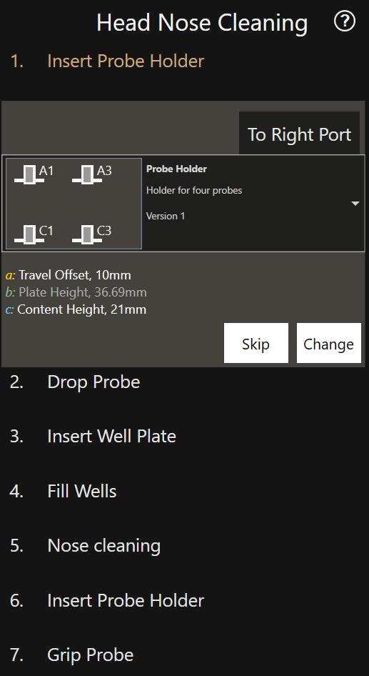
Standard head nose cleaning
This workflow is used to remove residues from the head nose. After removing the iontip, the head nose is dipped into distilled water, IPA and then dried in air. The total time required for this workflow is 45 minutes, however a longer period of 1-2 hours afterwards is advisable to let the sealing screw o-ring or the silicon tube dry completely.
Danger: Head nose damage
This workflow requires the removal of the iontip from the printing head. Exposing the head nose can result in damage to the head. Please pay attention during this procedure.
Prerequisites
- The system is calibrated.
- A trained operator is present.
- Clean distilled water and isopropanol are available.
Process
- Activate the Maintenance mode.
- Select the
Head Nose Cleaningworkflow. - Follow the instructions in the software.
Info: Aborting cleaning sequence
Once the cleaning sequence is initiated, it can be aborted by clicking on the red X in the wash tool or by leaving the workflow.
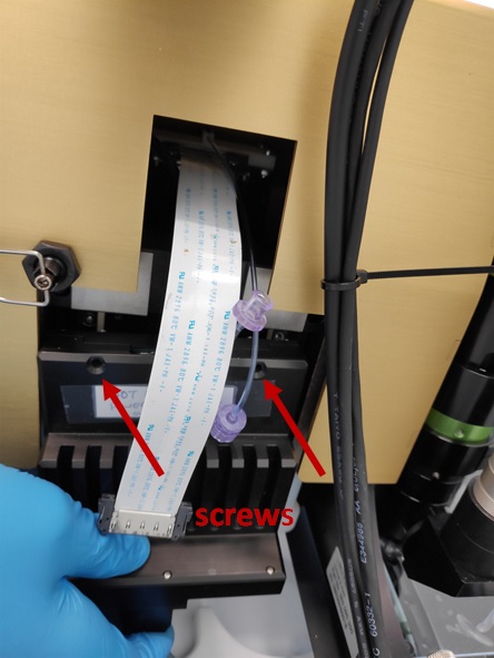
Head removal
Prerequisites
- Ensure a iontip is mounted before starting the procedure in order to protect the nose.
- The software is closed.
- Both pressure and system controllers are powered off.
Process
-
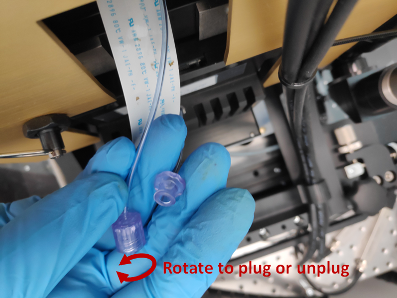
Rotate the luer lock to unplug the pressure tube.
-
Unplug the head cable by pressing the clips on the sides.
-
Hold the head with one hand and unscrew the two screws with a SW 2.0 screwdriver. Note that screw cannot be removed from the head.
-
Keeping the head in one hand, slightly tilt it out and pull it up from its socket. Push the Z stage down can help releasing the head.
Deep head nose cleaning
Over time, ink can deposit on the printing nose and sealing area; keeping the head clean helps to prevent leaks and ensures the performance and reliability of the system.
Info
Depending on your nose sealing method (sealing screw or silicon tube), there are two procedures for cleaning the nose. Make sure to read the instructions adapted to your hardware configuration.
Prerequisites
- The head is removed from the Z stage.
Process - sealing screw configuration
Warning
Removing the o-ring is a delicate operation that may cause permanent damage to the head if not done carefully. It is recommended to contact Exaddon customer support prior to performing this operation for guidance and instructions.
-
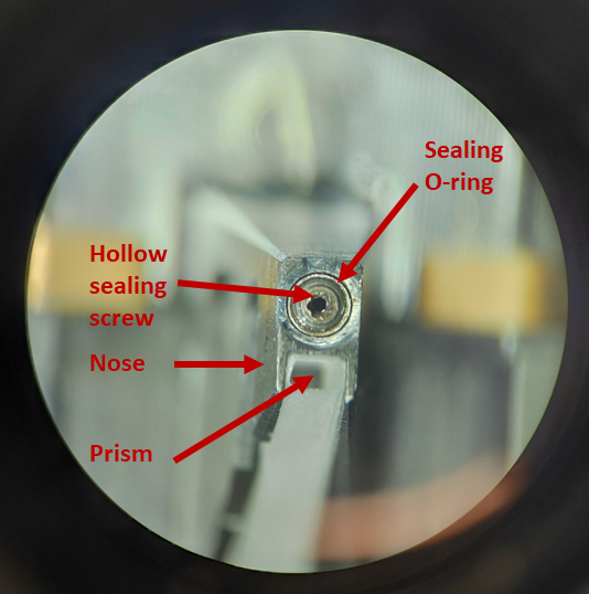
Insert a lever or a T1x40 screwdriver into the gripper’s hole and push to open them. Remove the consumable and let the grippers close again. The nose is composed of the parts shown below:
-
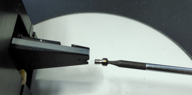
If crystals or particles are present, these need to be removed to ensure a proper sealing with the iontips. Remove the sealing screw with a T1x40 screw driver.
-
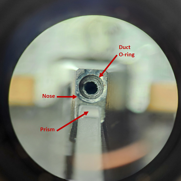
If the duct O-ring also need cleaning, remove the duct O-ring from inside the nose piece or the bottom of the sealing screw with tweezers.
-
Proceed to the required steps below to clean the nosepiece, O-rings and the sealing screw:
- To remove any water-soluble salts or stains (e.g. copper sulfate crystals from a Cu-based ink), dip the removed parts in deionized water. Suggested standard procedure is 3 min sonication in deionized water.
- Isopropanol (IPA) can be used to clean the O-rings and the sealing screw from non water-soluble products. Then, clean with water.
- For the nosepiece, wet a cotton swab with deionized water and use it to remove water-soluble products. Use cotton swabs with IPA to remove non water-soluble products. Be careful to not wet or stain the prism during this operation.
- Repeat any of those step if needed.
- Optional step: if you have access to clean a clean compressed gas supply like N2, apply a gentle flow from the head luer. This will ensure the channel and the silicon tube are not clogged, and remove any excess water or IPA from the cleaning. Make sure to not wet or stain the prism during this operation. Never perform this step with a non-clean gas supply like non-filtered compressed air as it may contain oil or dust particles that can damage the system.
- Let all the parts dry for 1-2 hours at ambient conditions.
- If the cleaning was not successful, it is advised to change the stained parts (O-ring or screw) for new parts.
- Damaged O-rings (deformed, flattened, hardened or cut) should be replaced.
Note
Due to capillarity effects, water can from a droplet inside the nosepiece channel during the cleaning. If the drying time is not long enough and the head is reassembled, this water in the pressure channel will degrade or prevent the functionality of the system. A dry cotton swab can be used to remove most of the excess water, but step 6 is mandatory. Apply gentle pressure and pay close attention to not wet or stain the prism.
Process - silicon tube configuration
Warning
The silicon tube is not supposed to be removed from the nose. If after following the steps below, the head still needs to be cleaned, it is recommended to contact Exaddon customer support for guidance and instructions.
-
Insert a lever or a T1x40 screwdriver into the gripper’s hole and push to open them. Remove the consumable and let the grippers close again.
-
Proceed to the required steps below to clean the nosepiece and the silicon tube:
- Isopropanol (IPA) can be used to clean the silicon tube from non water-soluble products. Then, clean with water. Small particles may be stuck in the silicon, preventing it from sealing prperly. If that is the case, try removing them using a cotton swab with water. If the particles cannot be removed, please contact Exaddon customer support for guidance and instructions.
- For the nosepiece, wet a cotton swab with deionized water and use it to remove water-soluble products. Use cotton swabs with IPA to remove non water-soluble products. Be careful to not wet or stain the prism during this operation.
- Repeat any of those step if needed.
- Optional step: if you have access to clean a clean compressed gas supply like N2, apply a gentle flow from the head luer. This will ensure the channel and the silicon tube are not clogged, and remove any excess water or IPA from the cleaning. Make sure to not wet or stain the prism during this operation. Never perform this step with a non-clean gas supply like non-filtered compressed air as it may contain oil or dust particles that can damage the system.
- Let all the parts dry for 1-2 hours at ambient conditions.
- If the cleaning was not successful, please contact Exaddon customer support for guidance and instructions.
Note
Due to capillarity effects, water can from a droplet inside the nosepiece channel during the cleaning. If the drying time is not long enough and the head is reassembled, this water in the pressure channel will degrade or prevent the functionality of the system. A dry cotton swab can be used to remove most of the excess water, but step 4 is mandatory. Apply gentle pressure and pay close attention to not wet or stain the prism.
Prism cleaning
A poor laser signal quality with more than one iontip can happen when the prism is dirty. Remove the head and follow the steps below to clean the prism if stains or dirt are noticed:
- Wet lint-free cleaning optical grade wipes with a 50/50 % mix of isopropanol (IPA) and ethanol.
- Rub the prism surface to remove dust and stains. Do not apply force as it may scratch the surface.
- If marks persist, start again. Depending on IPA quality, white evaporation marks may be left on the prism. In that case, start again.
- Let the prism dry for 1-2 hours as IPA may have wet the inside of the nose.
Reassembling the head
Steps 1-3 of this section only apply to heads with the sealing screw configuration. If you have the silicon tube configuration, you can directly go to step 4.
After cleaning, assemble the ring and sealing screw in reverse order:
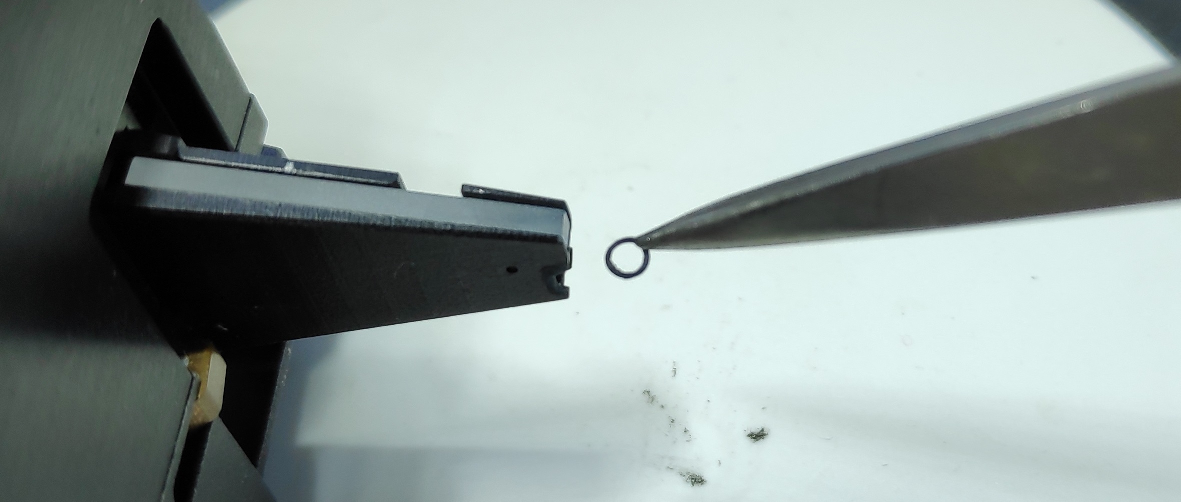
- Put the duct O-ring in the nose with tweezers and ensure it rests at the bottom of the hole.
- Screw and tighten the sealing screw. To drive the sealing screw correctly, first rotate it anticlockwise until the thread step is passed, then screw it clockwise until the dead stop, without applying extra force:
- Put the sealing O-ring on the sealing screw.
-
Mount an iontip on the nose using a lever in the gripper’s hole. Ensure the sealing screw enters the iontip reservoir and does not rest on the reservoir’s border.
Warning
Make sure no plate is installed in the XY sled as the tip may crash into a plate during the head installation.
-
Slide down the head to make sure the stud at the back of the head rests in the corresponding socket on the Z stage.
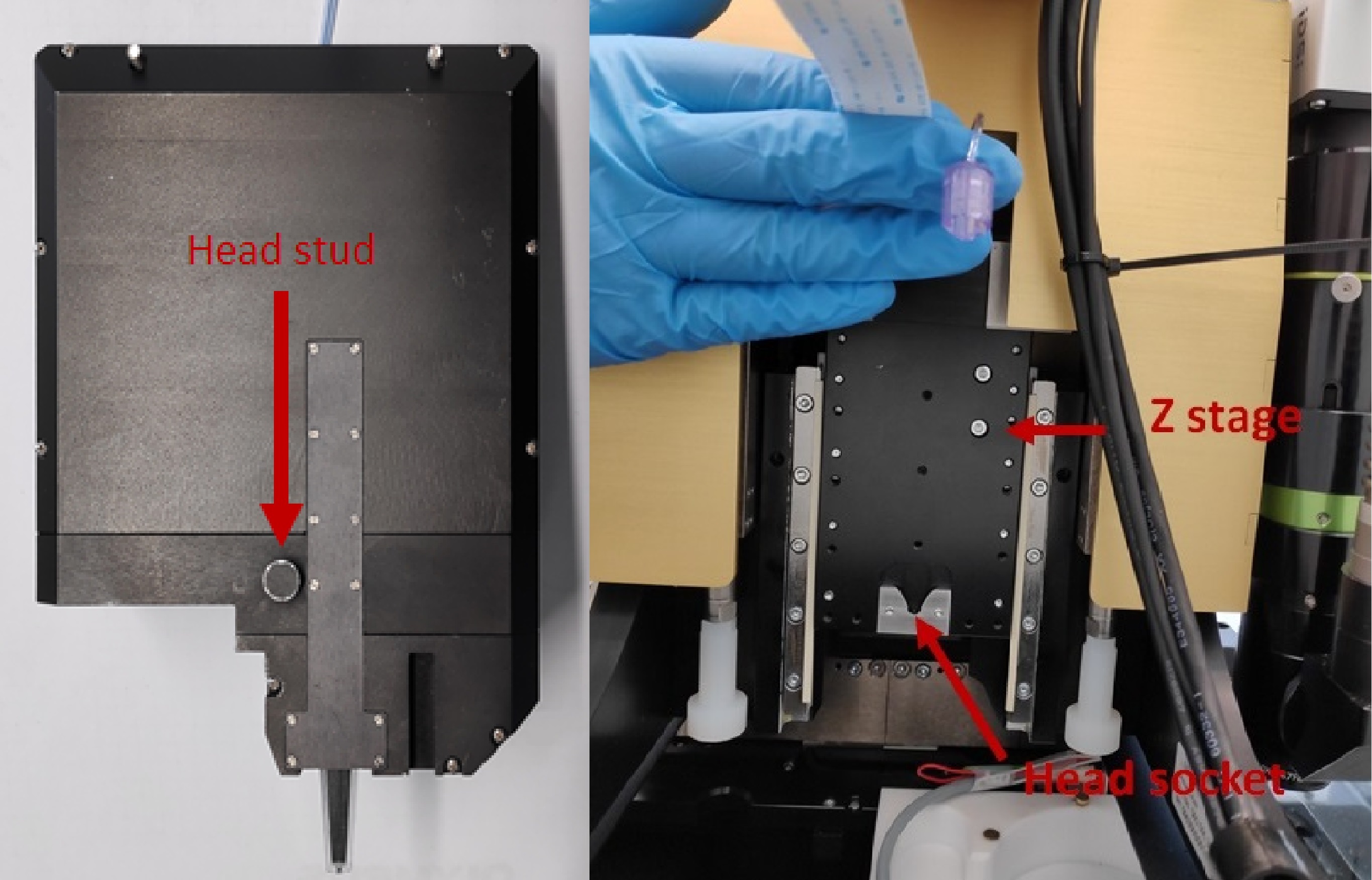
-
Fix both screws with a SW 2.0 screw driver.
- Connect the head cable. Both clips click when correctly plugged in.
- Connect the pressure tube and rotate the threaded part to tighten the luer lock. Make sure the thinner parts of the lock do not bend.
- Plug back in the mini-USB cable at the back of the controller.
- Power the pressure controller and system controller on.
- Start the software and let the system initialize itself.
- Enter the maintenance mode and perform the following calibration steps as the head and tip may not be in the same position as before due to assembling tolerances:
Calibrate XY (Head)Calibrate Z heightTop Camera alignmentMeasure top camera offset
Once the calibration is completed, the system is ready to be used again.