Troubleshooting common issues
Common issues encountered, their possible causes and solutions are reported in this page. If this troubleshooting chapter did not solve or list the issue, please contact the support at [email protected] for assistance.
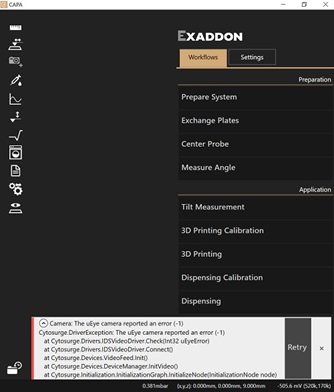
The software reports an error at start-up
Errors at start-up may happen because of communication issues between a component of the system and the computer:
- A component of the system is not powered on.
- A cable is not plugged in correctly.
- The controllers did not have enough time to boot completely. Please wait 1 min before restarting the software.
If the issue persists after a software restart, the whole system can be rebooted.
Axis disabled or dragging error
To avoid damage, axes are disengaged when too much force or friction is measured during their movement. Common sources of axis disengagement are:
- Touching an axis or exchanging a plate disengaged the positioning system.
- Something is in the way of the XY sled or the Z stage and induced friction during the movement to the target position.
- The plate or printing chamber was not placed correctly. All plates should rest on their four edges/feet.
- Plate definitions are incorrect: plate types and defined heights must be correctly set in the Exchange Plate workflow for the plates used.
- Calibration offsets are wrong, inducing a shift between the plate definition and the actual accessible area. Calibrate the system again if this shift can be observed.
- Axes may lack lubricant. The Rail Lubrication should have been conducted less than 1 month ago and the last cleaning and oiling maintenance less than 6 month ago.
- The software reported a
Resources are busyerror: another action is pending. Wait for the previous action to complete and try again or restart the software.
To re-initialize a disabled axis, restart the software.
Probe is not gripped correctly
Hints that the gripping procedure was not conducted properly are:
- The cantilever appeared poorly centered after gripping (further than ~100 µm away from the center).
- An axis disengaged during gripping.
- The tightness test failed.
- Gripping from specific ports of the probe holder plate worked better than others.
- The software reported an
I2C error. Restart the software and drop the probe, replace it and grip it again.
Most of those issues can happen because of:
- The probe is not correctly placed in the probe holder plate.
- The probe holder plate is not placed correctly on the sled.
- O-ring and screw are dirty: the screw maintenance should be conducted and if needed, any damaged parts should be changed.
- The axes were not correctly calibrated. The head must be removed and the system must be recalibrated.
Probe is not dropped correctly
Do not apply pressure during the dropping procedure. There is the risk of staining the prism and O-ring if there is ink in the reservoir. The probe must be manually removed and the head cleaned if needed.
Possible reasons for a probe not dropping are:
- The probe was dropped in an already used slot.
- The system was not properly calibrated.
- The O-ring and screw are dirty.
- The probe dried out after a long period of time and is stuck to the screw.
Applying pressure does not result in the expected filling, flow or print
Tips usually take up to 1 min at 500 mbar to fill. Probable reasons of a larger delay are:
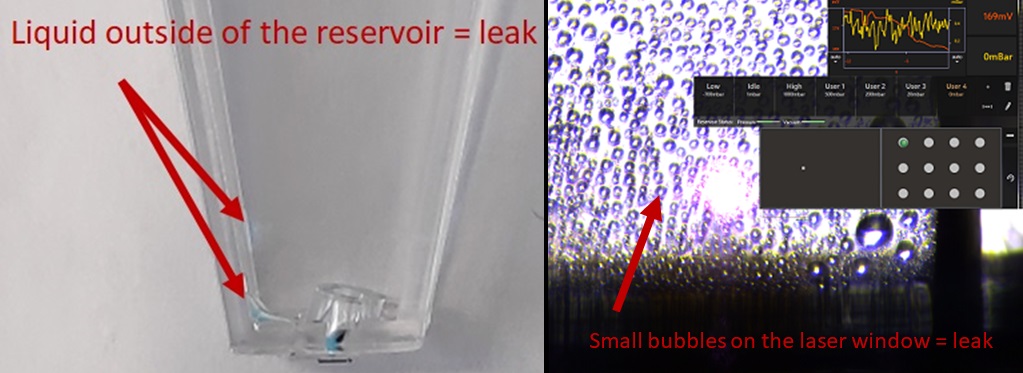
- The consumable leaked from the inside. Focus on the laser window to check for bubbles and drop the tip to check for any sign of ink inside the consumable but outside the reservoir.
- A smaller aperture and/or more viscous inks are used. Higher pressures are needed to properly fill and flow the probe in those conditions.
Ink must always be filtered before use (filters with max. 200 nm pores for 300+ nm apertures). If the tightness test is passed and the tip did not fill at 500 mbar after 1 min, higher pressures can be tested to fill the probe. Please report leaking chips and probes that did not fill after 1 min at 1 bar via e-mail for replacement. Conserve the reported probes until further notice.
Other flow issues can be:
-
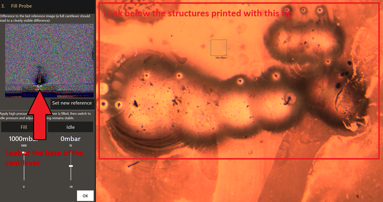
The probe leaks from the outside (leaking chip). The Fill Probe workflow can be used to observe abnormal flows close to the cantilever when it is immerged in liquid.
-
The flow is highly directional. The nanopipette is probably broken or partially clogged and may result in anisotropic printing performances. Replace the tip if it became unsuitable for printing.
-
The flow is much lower that expected, the probe is probably clogged. Dipping in a relevant etchant or solvent solution for few minutes can clean the aperture from deposited or aggregated material. The tip must then be cleaned from the etchant or solvent in water before printing again or changed if the performances were not improved by the cleaning step.
-
The flow is much larger than expected. Part of the cantilever probably broke, increasing the aperture opening and therefore, the flow. The pressure applied must be adapted to compensate for the larger flow or if the probe changed.
-
The probe or the inside of the hollow cantilever dried out after prolongated exposure to air (few minutes can be sufficient). This cannot be fixed and the tip must be changed.
-
The probe reservoir is empty. An empty reservoir could mean the probe leaked if it was not used intensively. Re-filling might not work if air becomes trapped in the microchannel.
-
The tip clogged while dispensing a particle suspension. Only particles small enough compared to the aperture can be dispensed (<1/5*diameter).
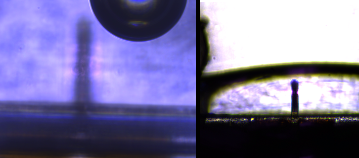
To check the flow of a tip, move it into the well of a wellplate filled with water, use the Fill probe step of the preparation workflow and apply 200 to 400mbar. The cloud of ink should appear around the tip on the differential image:
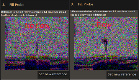
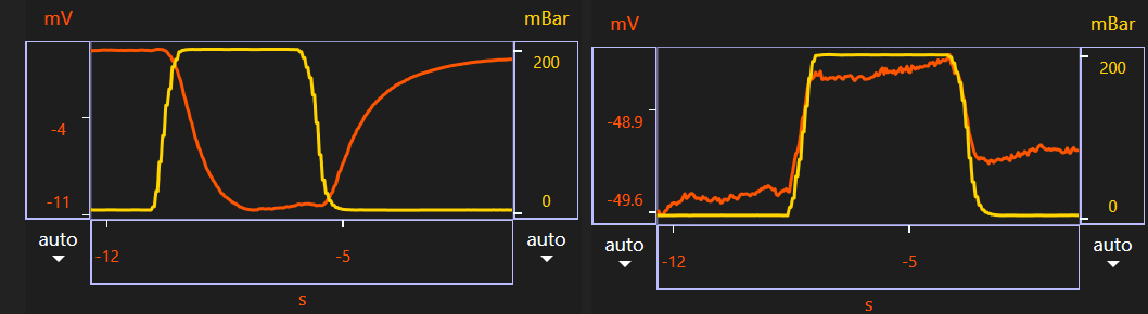
Alternatively when in liquid, an increase in pressure should lead to negative step on the laser signal, and a decrease in pressure, to a positive step (left image below). Clogged tips behave the opposite way (right image below):
Poor laser signal
Poor laser signal often takes the form of low signal level (<500mV on both diodes in the status bar), large noise on the base signal (>0.2 mV amplitude) or after a voxel trigger (>0.5 mV amplitude) in the deflection signal plotted with the LogViewer. Probable reasons for a poor laser signal after maximization are:
- The laser was not aligned properly. The optimum place is about the 2/3 to 3/4 of the cantilever length. Note that scattering through the plastic consumable may deform the apparent laser spot in an asymmetric manner. Alignment should be conducted with the probe’s reflective layer in focus.
- An air bubble formed after the probe was dipped into liquid. The bubble can usually be removed by dipping the consumable into a 50% ethanol-50% water solution, then in pure water. This can be repeated until the bubble disappears.
If the ethanol-water solution is not effective, the probe must be dropped and 15-30 µl of liquid has to be pipetted into the outer channel to remove all possible air. Please make sure a droplet always stays around the tip and pick the probe quickly as the cantilever must not dry out.
- The laser window, the prism or the reflective coating of the cantilever are dirty. Use the focus to search for bubbles, particles or stains on the laser path. If needed, unmount the head to check for prism stains and Clean the prism.
- Dirt or particles are floating in the liquid. Any particle moving in the laser path briefly decreases the signal quality.
- The cantilever broke. This happens if the tip becomes strongly trapped by the growing material during printing or after a collision.
Moving the laser by 1-10µm around its optimal position and maximizing the signal again can help to solve a noise or low signal issue.
The printing chamber does not behave as expected
If difficulties appear during printing despite having successfully performed the preparation workflow, the printing chamber might not work properly. This leads to dissolution or oxidation of the substrate’s Cu layer, patterns appearing on the surface of the substrate or no voxel printed despite having a flowing tip.
A negative current in the 0.2-2mA range is standard for the printing chamber v3 working in the Cu-SOP conditions, at -0.5V versus the AgCl reference electrode. The potential should quickly reach the target value while the current slowly reaches an equilibrium value with almost no noise, nor undercurrent or overcurrent. If copper-coated samples are used, it should stay bright and not dim, darken or display patters. The preparation of the chamber might be the cause:
- The wrong amount of supporting electrolyte was loaded in the chamber. Allowed amounts are 10 to 12mL to submerge all electrodes.
- Liquids were spilled or wet the outside of the chamber, especially at contacts with wires or the chamber was not tightened strongly enough during assembly. This could damage the chamber by dissolving contacts and losing control over the deposition potential on the substrate. Disassemble, wash and dry the cell immediately.
- An overaged or contaminated solution might not work as expected and must be regularly changed (~24-48h).
- There are poor electrical contacts. Resistances should be few ohms. Values can be checked using an ohmmeter between each electrode (WE/RE/CE) and the pins in the lemo plug.
- The chamber was not assembled properly.
Prints stop before reaching completion
By default, the system automatically cancels a print if no completed voxels are detected in a 1 min window. This timeout action and the timing can be changed in the 3D printing workflow options. Most causes can be identified trough analysis of the deflection and voxel time curves of the printfile with the LogViewer application. Main causes of timeouts are:
-
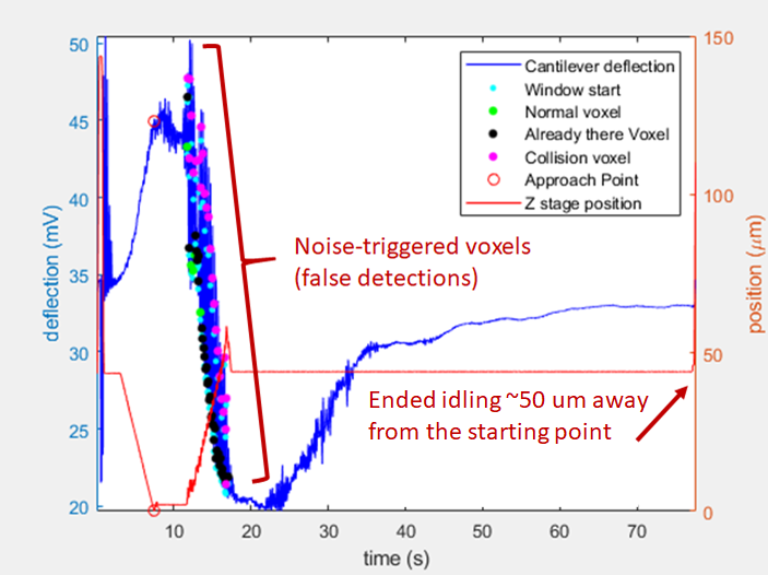
False detections of voxels (wrongly detected as printed) may lead the tip far from any printable surface and waiting for a trigger that takes too long to reach due to the distance to plate. False detections can happens because of crosstalk with the substrate reflection, stage movements, large pressure differences applied, noise or drift in the base signal.
Slightly repositioning the laser spot on the cantilever can be enough to increase signal-to-noise ratio. The voxel detection threshold can be increased at the expanse of a longer tip-structure contact time (higher clogging/breaking chances).
-
A false approach (early detection of a signal falsely interpreted as contact with the substrate) kept the tip away from the substrate. In these cases, the approach point deflection is not seen as a large positive impulse in the deflection curve. Simply retry the same printfile.
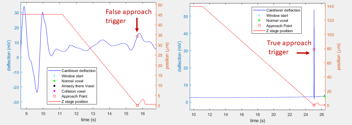
Note that the first example of false detection above is also a false approach event. -
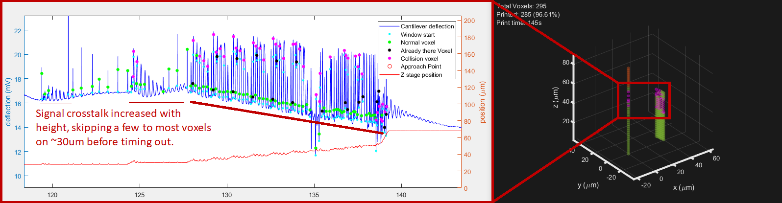
The tip clogged because of particles in the ink aggregating at the aperture or because material deposited and closed the aperture. The voxel time is increasing over time while printing parameters remained the same (voxel detection events are more and more time-spaced). Most of the time, the quick increase in voxel time is accompanied by an increase in the baseline level, indicating a sudden loss in flow. Note this is not seen in example 2 as the pressure used was small (40 mbar vs 300 mbar for example 1):
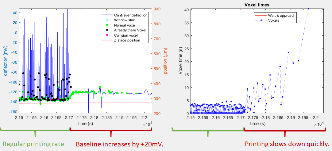
The tip must be changed unless dipping the tip in a solvent or etchant can unclog the aperture by dissolving the supposed clogging material (for example ethanol/IPA for additives or ferric chloride for copper). -
The printfile was poorly routed or designed, leaving the tip far away from any surface to plate on. This is likely if timeouts happens around the same position each time.
-
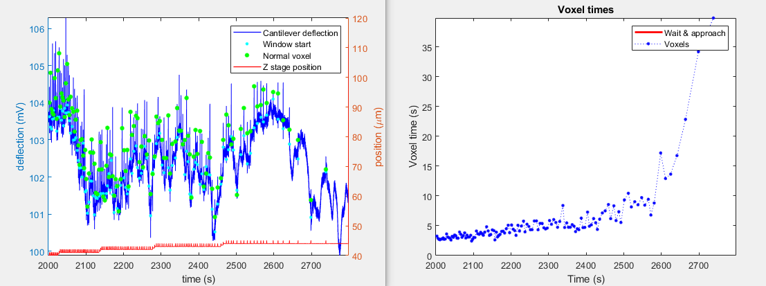
The reservoir of the consumable emptied. Symptoms are similar to a clogging tip since the ink flow decreases when the reservoir empties.
- Look for a poor laser signal if false detections are observed on the deflection signal (see the laser signal chapter above).
- Check the flow of the tip if the printing speed decreased or the printer did not start to print (see the pressure related chapter above).
- Look for clues about the potential control in the printing chamber if the tip flows but does not print (see chapter about the printing chamber above).
How to reboot the controller
If the controller returns an error and restarting the software doesn’t help, you might need to reboot the controller. Execute the following steps to do this:
- Turn the controller off
- Unplug the mini-USB cable otherwise the controller can still draw power via USB
- Wait 1 min
- Plug USB back in
- Turn the controller on
- Wait 1 minute
- Start the printing software
How to send log files
If you encounter an error or unexpected behavior in the software, you can send us an e-mail with the log files attached. There are two types of log files which are of interest for us.
CAPA log file
- Open the software
- Press F12 to open the directory containing the log files
- Select all files in the directory
- Right click and select Send to -> Compressed (zipped) folder
- Use the newly created ZIP file as an e-mail attachment
Event Viewer
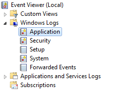
- Open the start menu, type eventvwr.msc and press Enter
-
Choose Windows Logs -> Application
-
Apply a filter to only show events from the .NET Runtime
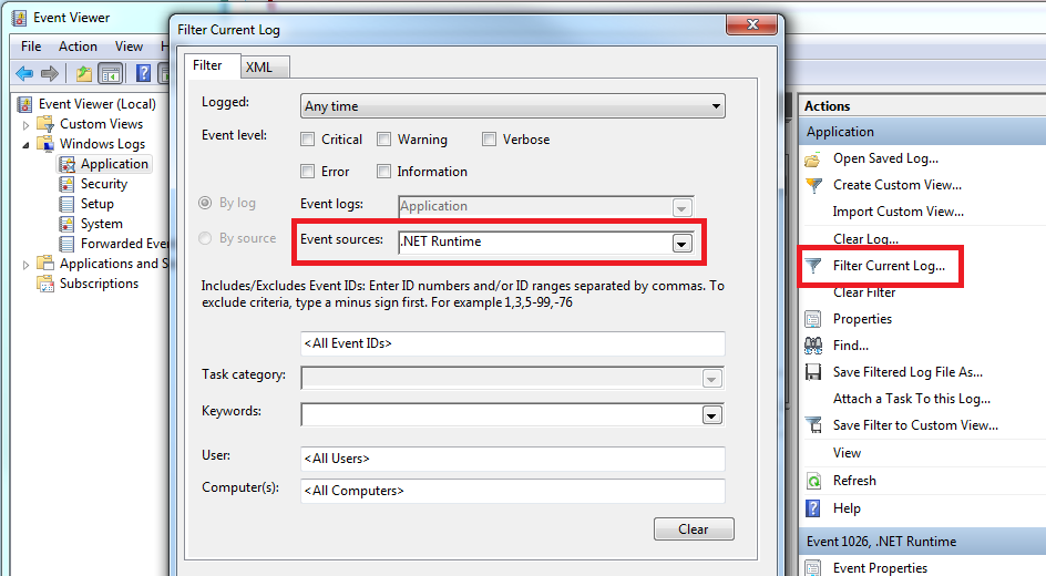
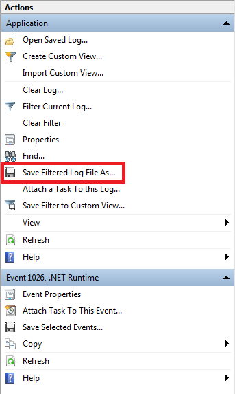
-
Export the events to a file and use it as an e-mail attachment
Providing context
In addition to log files, providing context can prove useful to find, reproduce and correct errors:
- How can the the issue be reproduced? What steps led to the error?
- A screenshot of the software showing the error message encountered can be sent with the mail in addition to the log files and context. If available, expand the error message.